

Attitude adjusting method in imaging along oblique strip
An adjustment method and oblique strip technology, applied in attitude control and other directions, can solve problems such as difficulty in ensuring imaging quality during maneuvering, inability to realize oblique strip imaging attitude planning, and lack of imaging drift angle compensation.
- Summary
- Abstract
- Description
- Claims
- Application Information
AI Technical Summary
Problems solved by technology
Method used
Image

Examples
Embodiment Construction
[0060] Below in conjunction with accompanying drawing and specific embodiment the present invention will be described in further detail:
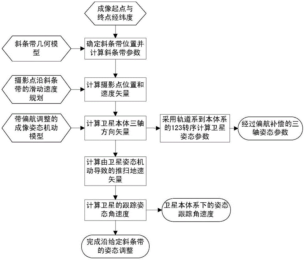
[0061] Such as figure 1 The method flow chart shown in the present invention aims at imaging along the oblique strip, on the basis of planning the sliding speed of the imaging point along the oblique strip, and realizes the tracking of the imaging point and the drift angle compensation of the imaging by establishing the imaging attitude maneuver model , the three-axis attitude and attitude tracking angular velocity of the camera carrier (satellite, spacecraft, etc.) during the imaging process along the oblique strip are obtained, and the attitude adjustment for imaging along a given oblique strip during attitude maneuvering is realized.
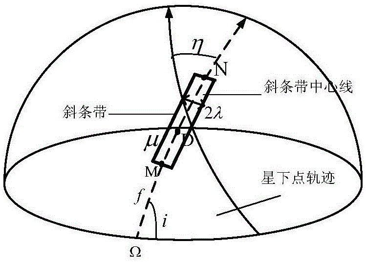
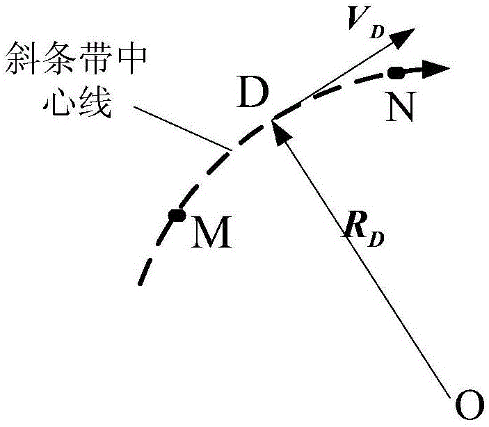
[0062] (1) Determination of geometric parameters of oblique strips
[0063] established as figure 2 In the oblique strip model shown, a circular arc with the center of the earth as the center is formed ...
PUM
 Abstract
Description
Claims
Application Information