Current transformer

A technology of current transformers and mutual induction coils, which is applied in the direction of inductors, voltage/current isolation, transformers/inductor coils/windings/connections, etc., which can solve problems such as output distortion of current transformers, improve accuracy and reduce design The effect of manufacturing difficulty and preventing low-load dead zone

Inactive Publication Date: 2015-10-28
STATE GRID SHANDONG ELECTRIC POWER +1
View PDF5 Cites 2 Cited by
  • Summary
  • Abstract
  • Description
  • Claims
  • Application Information

AI Technical Summary

Problems solved by technology

[0003] According to the deficiencies in the prior art above, the technical problem to be solved by the present invention is: provide a current transformer, overcome the problem of output distortion of the current transformer at low load, improve the measurement accuracy, and reduce the economic loss of the power grid

Method used


Image

  • Current transformer

Examples


Embodiment Construction

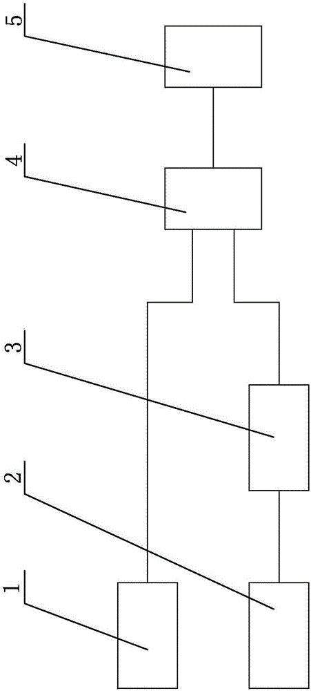
[0012] Embodiments of the present invention are further described below in conjunction with accompanying drawings:

[0013] Such as figure 1 As shown, the current transformer includes a mutual induction coil. The mutual induction coil is composed of a closed iron core and a winding. There are two groups of mutual induction coils, which are respectively the first mutual induction coil 1 and the second mutual induction coil 2. The ratio of the number of turns of the secondary winding to the number of turns of the primary winding is N1, the ratio of the number of turns of the secondary winding of the second mutual induction coil 2 to the number of turns of the primary winding is N2, and N2 is greater than N1; the first mutual induction coil 1 is connected to the comparison circuit 4, the second The two mutual induction coils 2 are connected to the amplifying circuit 3, and the amplifying circuit 3 is connected to the comparing circuit 4, and the amplification ratio of the amplify...


PUM


Abstract

The invention relates to the field of electric power system automation, and specifically relates to a current transformer. The current transformer comprises mutual inductance coils composed of closed iron cores and windings. The mutual inductance coils comprise two groups, namely a first mutual inductance coil and a second mutual inductance coil. The ratio of the number of turns of the secondary winding of the first mutual inductance coil to the number of the primary winding of the first mutual inductance coil is larger than the ration of the number of turns of the secondary winding of the second mutual inductance coil to the number of the primary winding of the second mutual inductance coil. The first mutual inductance coil is connected to a comparison circuit, the second mutual inductance coil is connected to an amplification circuit, and the amplification circuit is connected to the comparison circuit. According to the invention, an output distortion problem of the current transformer under a low load condition is solved, the metering accuracy is improved, and the economic loss for the power grid is reduced.

Description

technical field [0001] The invention relates to the field of power system automation, in particular to a current transformer. Background technique [0002] The principle of current transformer is based on the principle of electromagnetic induction. A current transformer consists of a closed core and windings. Its primary winding has very few turns, and it is connected in series in the line of the current to be measured, so it often has all the current of the line flowing, and the secondary winding has a large number of turns, connected in series in the measuring instrument and the protection circuit, and the current mutual inductance When the transformer is working, its secondary side circuit is always closed, so the impedance of the series coil of the measuring instrument and the protection circuit is very small, and the working state of the current transformer is close to a short circuit. The current transformer is used to convert the large current on the primary side in...

Claims


Application Information

Patent Timeline
Patent Type & Authority Applications(China)
IPC IPC(8): H01F38/28H01F38/32H01F27/28G01R15/18
Inventor 邱晨王屹尹相国魏汝东王毅王会诚王慧丽于洋郭中华杨雷鹏牛明张华傅乐王前邓效勇叶亮
Owner STATE GRID SHANDONG ELECTRIC POWER
Why Eureka
Try Eureka