
Cooling device for a motor vehicle

A technology for cooling devices and motor vehicles, which is applied in the arrangement of cooling combined power units, power units, heating/cooling equipment, etc., can solve the problems of expensive assembly and disassembly, and achieve simplified assembly, simplified assembly, and balanced manufacturing tolerances. Effect

Active Publication Date: 2015-10-28
VOLKSWAGEN AG
View PDF10 Cites 7 Cited by
  • Summary
  • Abstract
  • Description
  • Claims
  • Application Information

AI Technical Summary

Problems solved by technology

[0007] The arrangement or construction of the fastenings on the cooler block for the cooling air housing or the cooling air supply hood surrounding the cooler block is relatively expensive in terms of manufacturing costs due to metalworking processes, but also in terms of assembly and disassembly

Method used


Image

  • Cooling device for a motor vehicle
  • Cooling device for a motor vehicle
  • Cooling device for a motor vehicle

Examples


Embodiment Construction

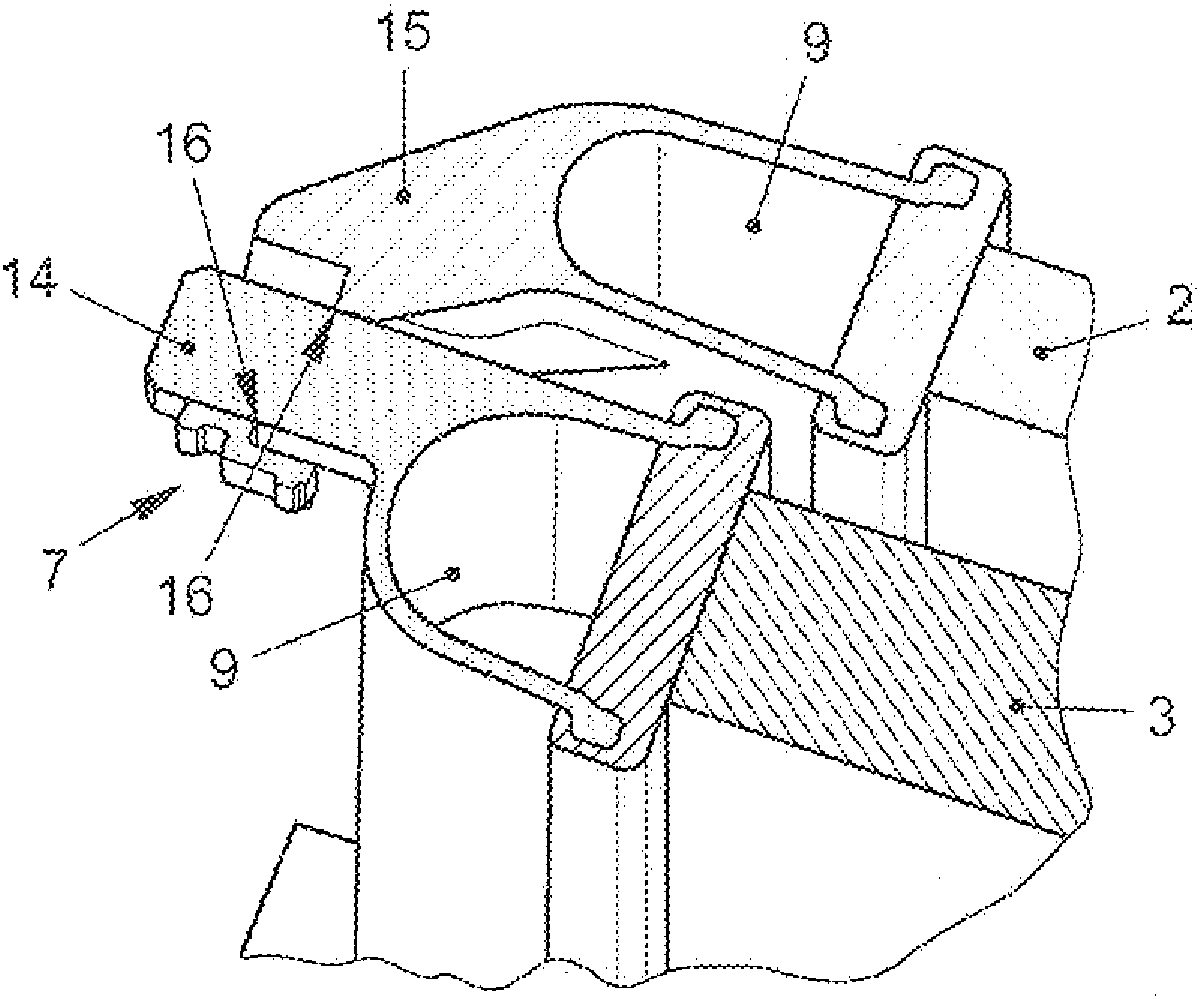
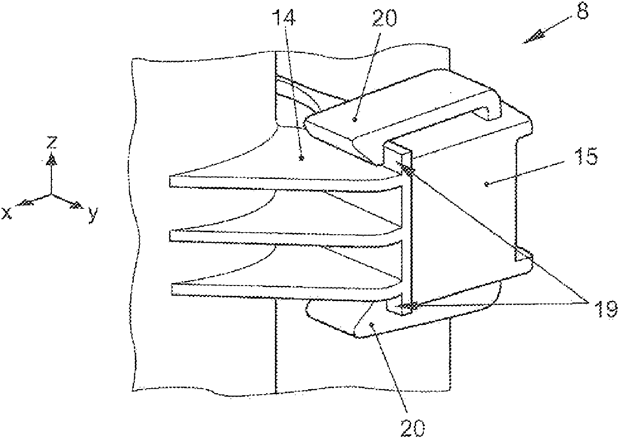
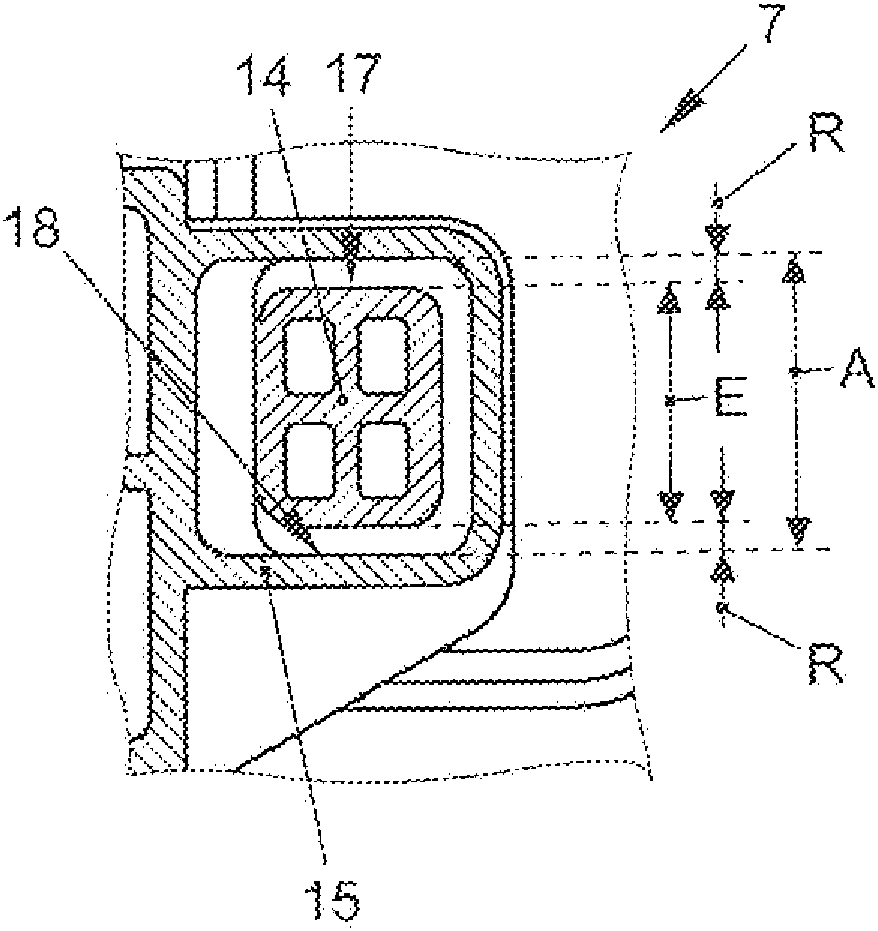
[0061] figure 1 Shown is a cooling device 1 for a motor vehicle, not further shown. The cooling device 1 comprises a low temperature cooler 2 and a high temperature cooler 3 as cooling elements 2 , 3 . Further cooling elements 4 , 5 are fan housing 4 and condenser 5 . At least the cooling elements 2 , 3 are arranged in different parallel planes in such a way that the supplied ambient air can flow one after the other. A flange 6 for connecting the cooling device 1 to the vehicle is formed on the subcooler 2 . All forces of the cooling device 1 are guided into the vehicle via the flange 6 . The other cooling elements 3 , 4 , 5 are fixed indirectly and / or directly on the cryocooler 2 . To connect the cooling elements 2 , 3 , 4 , 5 , in particular the low temperature cooler 2 and the high temperature cooler 3 , to one another, plug connections 7 , 8 are provided. The plug connections 7 , 8 are arranged at opposite edges of the cooling elements 2 , 3 , 4 , 5 . In the shown lo...


PUM


Abstract

The invention relates to a cooling device for a motor vehicle, wherein the cooling device comprises at least two cooling elements (2, 3), which are arranged in succession in different, in particular parallel, planes so as to be permeable to supplied ambient air and which are interconnected by means of plug-in connections, wherein at least one first plug-in connection (7) is disposed so as to be displaceable along a first spatial axis during assembly and at least one second plug-in connection is disposed so as to be displaceable along a second spatial axis transversally to the first spatial axis during assembly, and the at least one of the first plug-in connections (7) is disposed so as to be limitedly displaceable in the direction of at least one spatial axis in its fixing position, which connects the cooling elements (2, 3), in the plane parallel to the cooling elements (2, 3) in each case. The at least one first plug-in connection (7) is arranged on a first edge, in particular on a first collecting device (9) of the cooling elements (2, 3), so as to form a floating bearing face, and the at least one second plug-in connection is arranged on a second edge lying opposite the first edge, in particular on a second collecting device (9), so as to form a fixed bearing face.

Description

technical field [0001] The invention relates to a cooling device for a motor vehicle, wherein the cooling device comprises at least two cooling elements which are arranged in different, in particular parallel, planes so that supplied ambient air can flow one behind the other and are interconnected by means of plug connections, wherein at least one first plug connection is movable in a first direction and at least one second plug connection is movable in a second direction transverse to the first direction, and In its fixed position connected to the cooling element, at least one of the first plug connections is accordingly designed to be movable in a manner that is limited in at least one direction in a plane parallel to the cooling element. Background technique [0002] Subcoolers, also known as subcoolers, are used in modern internal combustion engines for intercooling (Rueckkuehlung) and are used to cool the water of the engine. Often a low-temperature cooler is used inst...

Claims


Application Information

Patent Timeline
IPC IPC(8): B60K11/04F28F9/00
CPCF28D1/0435B60K11/04F28F9/002F28F2275/08B60H1/00528
Inventor M.罗尔
Owner VOLKSWAGEN AG
Learn More