
Flow-turned brake disc

A technology of flow forming and brake discs, which is applied to the application of the brake discs, friction rings and brake disc chambers, and the field of manufacturing brake discs, can solve the problems of minimum wall thickness, increased weight, high cost, etc., to prevent Subsequent warping, cost-saving effect

Active Publication Date: 2015-10-28
THYSSENKRUPP STEEL EURO AG
View PDF8 Cites 0 Cited by
  • Summary
  • Abstract
  • Description
  • Claims
  • Application Information

AI Technical Summary

Problems solved by technology

In addition to the contact problem between the two dissimilar metals in these discs, the disc housing also needs to be manufactured separately and thus leads to higher costs
Furthermore, for friction rings made of cast steel, the problem of minimum wall thickness and the increased weight in this respect still exist

Method used


Image

  • Flow-turned brake disc
  • Flow-turned brake disc
  • Flow-turned brake disc

Examples


Embodiment Construction

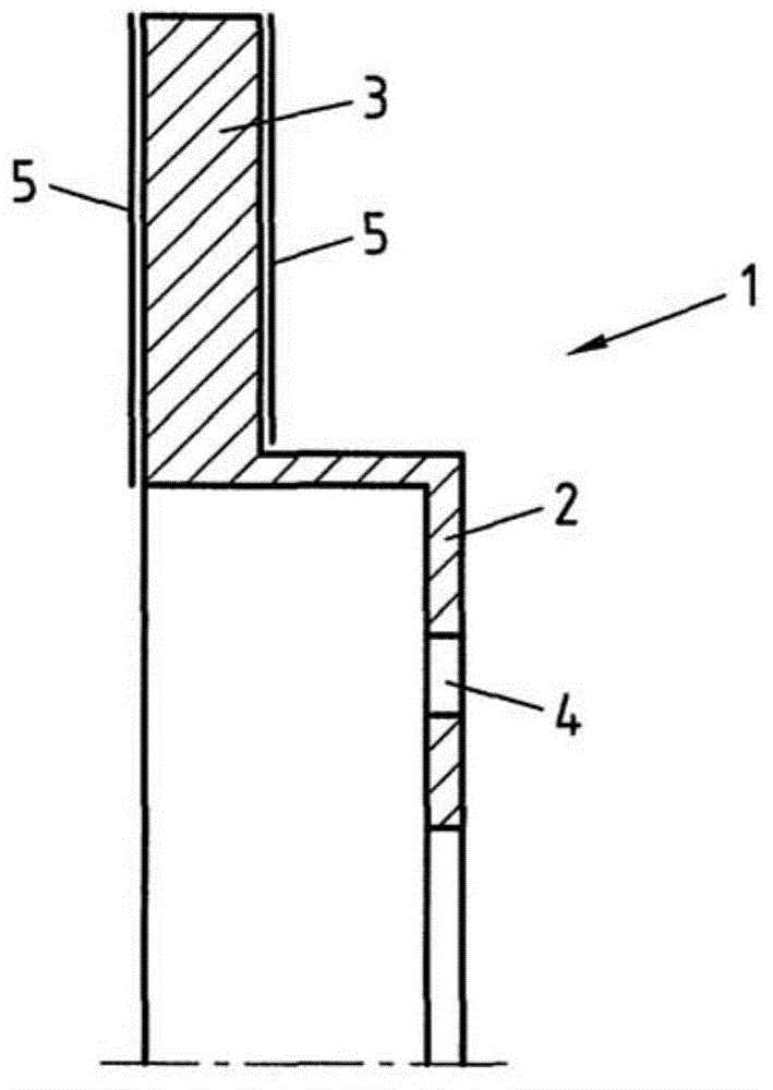
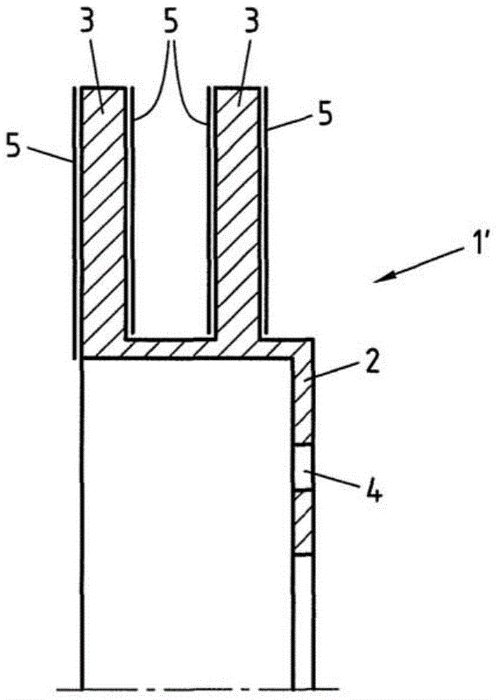
[0024] figure 1 A half of a cross-sectional view of an exemplary embodiment of a brake disc according to the invention is shown. The brake disc 1 includes a brake disc chamber 2 and a friction ring 3. During braking, the friction ring 3 establishes contact with a brake pad (not shown), so that the friction on the friction ring 3 is used to brake the rotation of the brake disc 1. According to the present invention, the brake disc chamber 2 and the friction ring 3 are integrally designed from the flow forming material. This achieves the substantial advantage that firstly the connection between the friction ring and the brake disc chamber has the greatest strength. Secondly, due to the flow forming process or the flow spinning process, materials other than cast materials can be used to manufacture the brake disc, so that a sufficiently low wall thickness can be achieved. In addition, another advantage compared to other lightweight solutions is that due to the integrated design o...


PUM


Abstract

A brake disc for a disc brake comprising a friction ring (3) and a brake disc hub (2), wherein the friction ring and brake disc hub of the brake disc are a single piece and consist of a flow-turned, heat-resistant or high temperature resistant steel grade.

Description

Technical field [0001] The invention relates to a brake disc of a disc brake, which comprises a friction ring and a brake disc chamber. The invention also relates to a method for manufacturing a brake disc, and also to the use of the brake disc. Background technique [0002] Disc brakes are a braking system commonly used in motor vehicles, cranes or elevators. In these examples, the disc brake includes a brake pad, which is usually pressed against a rotating brake disc, so that the rotational movement of the brake disc is braked. To this end, the brake disc includes a brake disc chamber, which has a cup shape and has a friction ring fixed to the brake disc chamber. The brake pads of the disc brake are pressed against the surface of the friction ring. The brake disc chamber is used to fix the rotating shaft, and the rotation of the rotating shaft will be braked. The brake disc chamber and friction ring are usually made of cast steel for mass production. Although it is possibl...

Claims


Application Information

Patent Timeline
IPC IPC(8): F16D65/12
CPCF16D65/125F16D2065/1308F16D2200/0021F16D2250/0023B21D22/14B21D53/26F16D65/12
Inventor 米夏埃尔·霍弗特
Owner THYSSENKRUPP STEEL EURO AG
Learn More