Magnetic brake

A technology of electromagnetic brakes and brake discs, applied in the direction of brakes, brake types, brake components, etc., can solve the problems of large force on the rotating body, braking impact, and the impossibility of applying industrial robotic arms, etc., to achieve the maximum installation space The effect of minimal constraints and compact structure production

Inactive Publication Date: 2015-10-28
KOHYOUNG TECH +1
View PDF5 Cites 10 Cited by
  • Summary
  • Abstract
  • Description
  • Claims
  • Application Information

AI Technical Summary

Problems solved by technology

[0004] However, with respect to the conventional electromagnetic brake as described above, if a voltage is applied to the brake shoe portion formed by the electromagnet, then the entire surface of the brake shoe portion and the entire surface of the brake disc portion are in close contact at the same time. A large frictional force is instantaneously generated between the brake shoe portion and the brake disc portion, so there is a problem that not only a large braking impact is applied to the rotating body during braking, but also the rotating body Instead of stopping slowly and softly, the body brakes sharply
[0005] Therefore, the above conventional conventional electromagnetic brake has the problem that it is practically impossible to apply it to an industrial robot arm that requires precise control or a surgical robot arm that requires more precise control.

Method used


Image

  • Magnetic brake
  • Magnetic brake
  • Magnetic brake

Examples


Embodiment 1

[0035] refer to figure 1 , the electromagnetic brake according to the first embodiment of the present invention will be described.

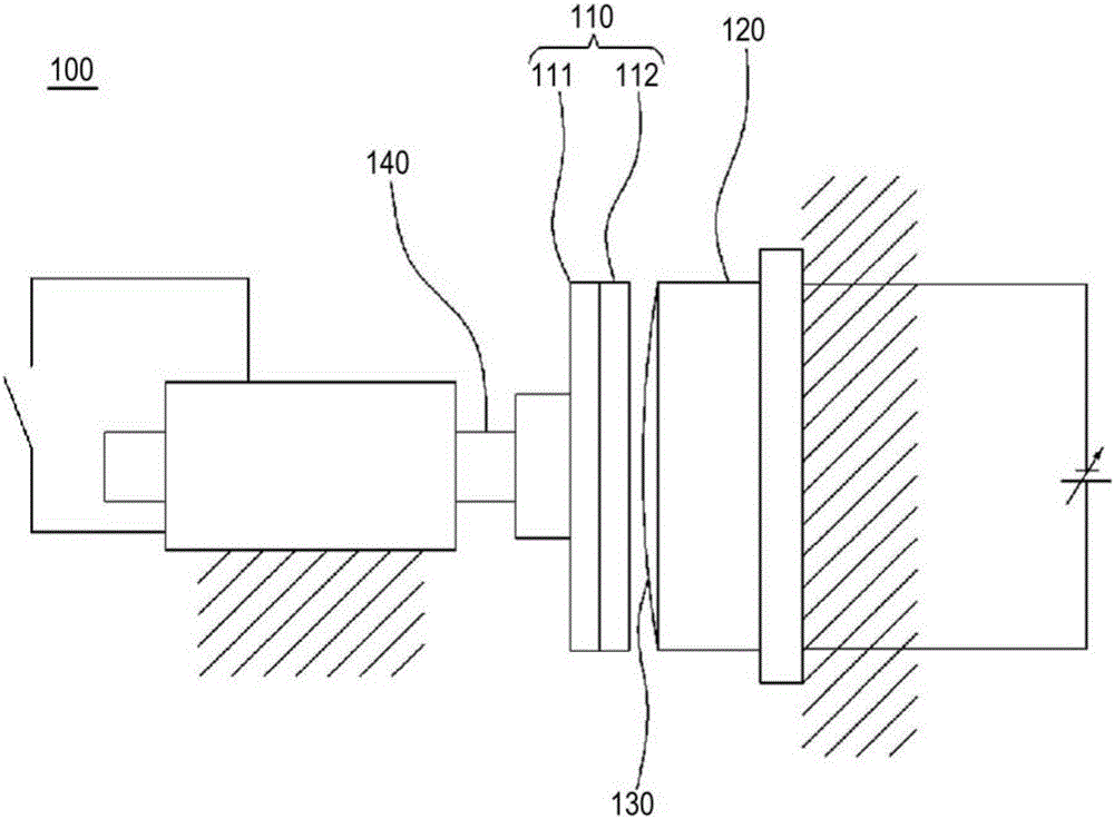
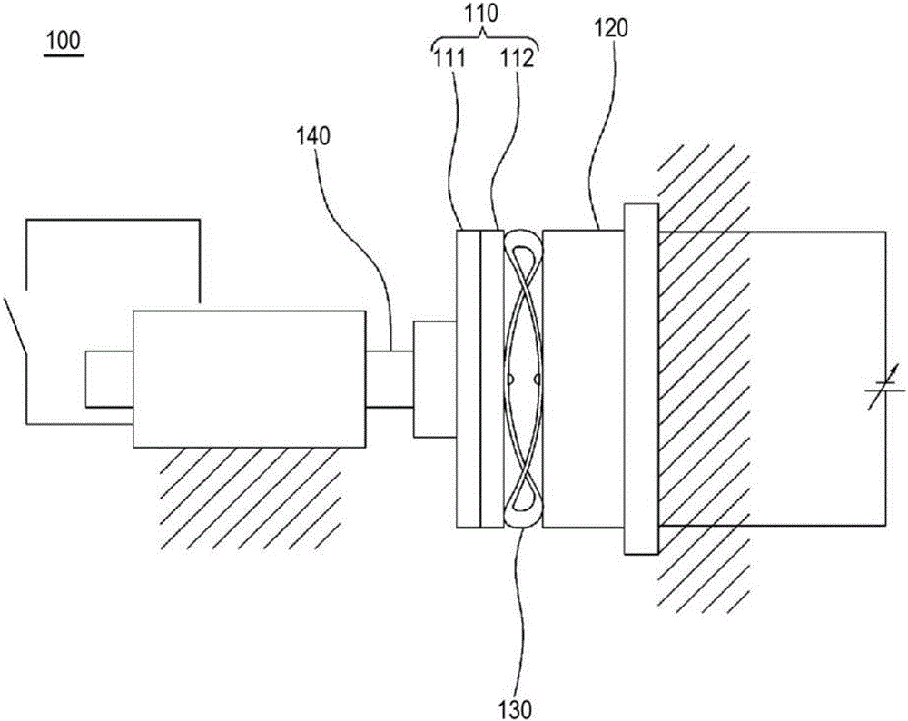
[0036] figure 1 is a schematic diagram of the electromagnetic brake of the first embodiment of the present invention, figure 2 is another schematic diagram of the electromagnetic brake according to the first embodiment of the present invention.

[0037] if refer to figure 1 and figure 2 , The electromagnetic brake 100 of the first embodiment of the present invention includes a brake disc portion 110 , a brake shoe portion 120 , and a buffer means 130 .

[0038] The brake disc portion 110 is axially mounted on the rotating body 140 so as to be able to rotate in conjunction with the rotating body 140 . Wherein, preferably, it is slidably mounted on the rotating body 140 in an axial manner, so that the brake disc portion 110 moves toward the brake shoe along the rotating body 140 when the power is connected to the brake shoe portion 120 . ...

Embodiment 2

[0050] refer to image 3 and Figure 4 , the electromagnetic brake according to the second embodiment of the present invention will be described.

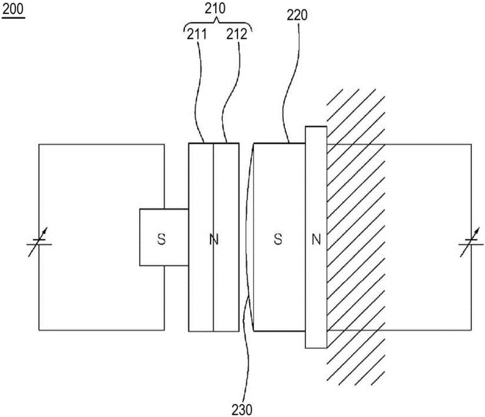
[0051] image 3 is a schematic diagram of an electromagnetic brake according to a second embodiment of the present invention, Figure 4 is another schematic diagram of the electromagnetic brake according to the second embodiment of the present invention.

[0052] The electromagnetic brake of this embodiment is the same as the electromagnetic brake of the first embodiment except for a part of the brake disc unit, and thus detailed descriptions of other constituent elements other than the part of the brake disc unit are omitted.

[0053] if refer to image 3 and Figure 4 , the brake disc portion 210 of the electromagnetic brake 200 according to the second embodiment of the present invention is mounted on the rotating body in a shaft manner so as to be able to rotate in conjunction with the rotating body (not shown in the figure...

Embodiment 3

[0063] refer to Figure 5 and Figure 6 , the electromagnetic brake according to the third embodiment of the present invention will be described.

[0064] Figure 5 is a schematic diagram of an electromagnetic brake according to a third embodiment of the present invention, Figure 6 It is a front view for explaining the structure of a shoe part.

[0065] The electromagnetic brake of this embodiment is the same as the electromagnetic brake of the first embodiment except for a part of the brake shoe part, so detailed descriptions of other constituent elements except for a part of the brake shoe part are omitted. For example, the same / similar constituent elements are assigned the same reference numerals. On the other hand, this embodiment may not include the buffering means disclosed in the first embodiment.

[0066] if refer to image 3 The brake shoe portion 320 of the electromagnetic brake 300 according to the third embodiment of the present invention is formed by concen...


PUM


Abstract

Disclosed is a magnetic brake for minimizing braking shock applied to a rotor by gradually increasing frictional force generated between a disk portion and a pad portion when braking the rotor and smoothly stopping the rotor. The magnetic brake has a very simple and compact structure thereby minimizing braking shock applied to the rotor and smoothly stopping the rotor, and thus can be made useful through an application to a joint portion of a robotic arm requiring precise control, is manufactured to have the simple and compact structure thereby minimizing limitations due to installation space, and can effectively render smaller and lighter various devices to which the magnetic brake is applied.

Description

technical field [0001] The present invention relates to an electromagnetic brake, and more specifically, to an electromagnetic brake capable of braking a rotating body. Background technique [0002] In general, as brakes for the purpose of dynamically braking the rotation of a rotating body, mechanical brakes and electromagnetic brakes are most widely used. The mechanical brake makes the brake shoe contact the rotating body with a mechanical structure, thereby Rotational motion is stopped by frictional force, and the electromagnetic brake utilizes magnetic force to bring a brake shoe into contact with a rotating body to stop rotational motion by frictional force. [0003] In the above-mentioned electromagnetic brake, when a voltage is applied to the brake shoe formed by the electromagnet, the brake disc provided in the rotating body moves toward the brake shoe, and the brake disc comes into close contact with the brake shoe. part, a frictional force is generated between the...

Claims


Application Information

Patent Timeline
Patent Type & Authority Applications(China)
IPC IPC(8): F16D65/28F16F1/32
CPCF16D65/28F16D2121/20B25J19/0004B60T13/748F16D63/002F16D65/186F16F1/32F16D27/04F16D27/14
Inventor 李秉周徐钟汰
Owner KOHYOUNG TECH
Why Eureka
Try Eureka