
A circulating type separation column capable of continuous sample injection

A separation column and circulating technology, applied in the field of circulating continuous sampling separation column, can solve the problems such as difficult to achieve continuous separation, and achieve the effect of easy assembly or disassembly maintenance, easy manufacture, and precise rotation angle

Active Publication Date: 2016-11-30
CHINA INSTITUTE OF ATOMIC ENERGY
View PDF3 Cites 0 Cited by
  • Summary
  • Abstract
  • Description
  • Claims
  • Application Information

AI Technical Summary

Problems solved by technology

[0003] However, at present, the column separation system with a high degree of automation is mostly used for the analysis of trace components, and the amount of tested samples is small. Therefore, intermittent analysis is mostly used, that is, one-time sample injection or single-column reuse. Difficult to achieve continuous separation

Method used


Image

  • A circulating type separation column capable of continuous sample injection
  • A circulating type separation column capable of continuous sample injection
  • A circulating type separation column capable of continuous sample injection

Examples


Embodiment 1

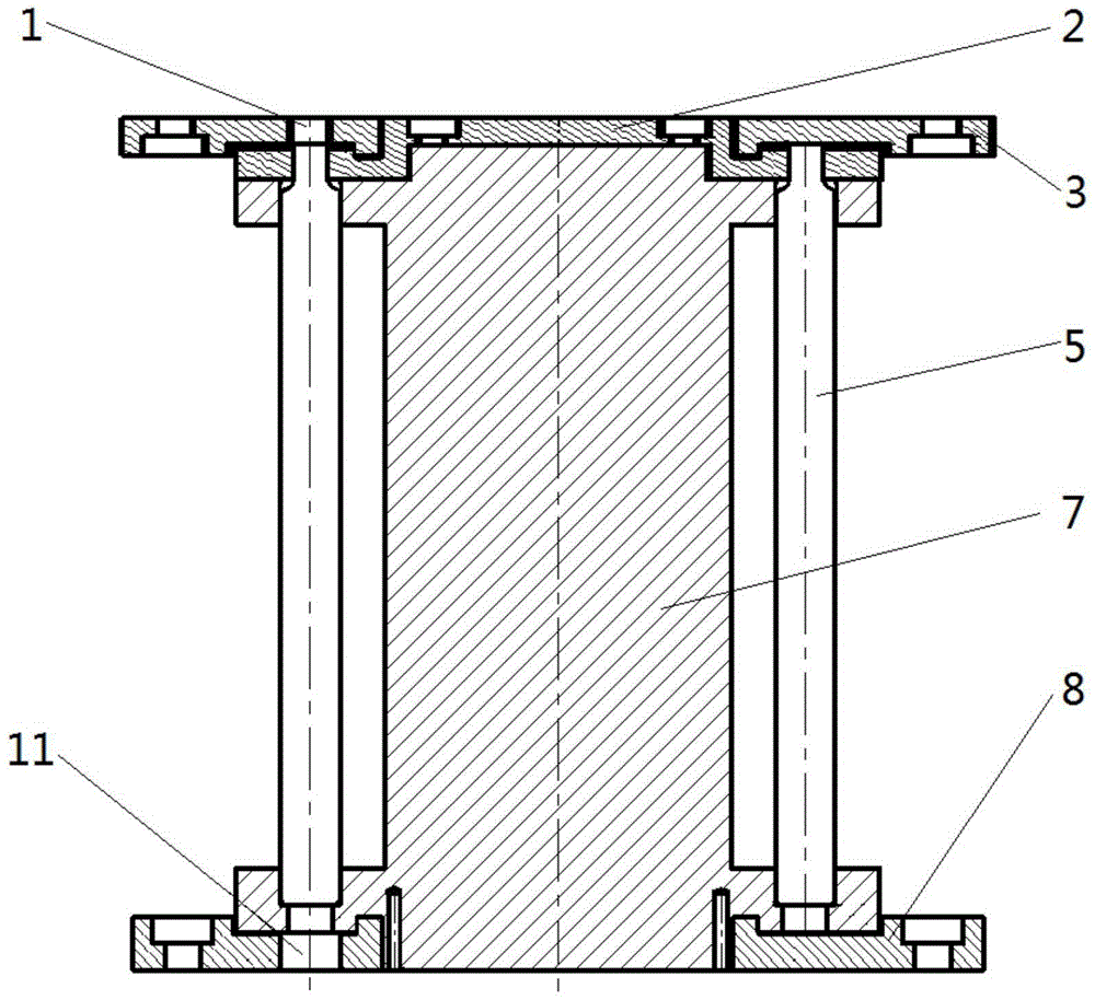
[0035] As described above, the circulating type can continuously inject samples into the separation column, the difference of this embodiment is that, as image 3 As shown, it is a cross-sectional view of a part of the structure of the cyclic continuous sampling separation column of the present invention.

[0036] combine Figure 4 As shown, it is a structural diagram of the upper platen of the circulating continuous sample injection separation column of the present invention; wherein, the upper platen 3 is a disc with the hole in the center, and the hole is a shaft hole, so that the upper platen 3 It is ring-shaped, and there is a ring-shaped groove on the inner side of the lower end surface of the upper platen 3, and there are multiple injection ports 1 in the groove; there are multiple mounting holes distributed on the outer side of the upper platen 3, which are used for fixed connection with the support column 4, The fixed connection can be a threaded connection, which is...

Embodiment 2

[0048] As mentioned above, the circulation-type separation column that can continuously inject samples is different from this embodiment in that there is an annular protrusion on the inner side of the lower end surface of the upper platen 3, and an annular groove on the outer side of the upper end surface of the glass tube cover 2, so The annular protrusion is in close contact with the annular groove.

Embodiment 3

[0050] As mentioned above, the circulation type can continuously feed the separation column, the difference of this embodiment is that the lower end surface of the glass installation cylinder 7 has an annular groove, and the inner side of the lower pressure plate 8 has an annular protrusion. The annular groove is in close contact with the annular protrusion.


PUM


Abstract

The present invention is a circular-type continuous sample introduction separation column comprising an upper press plate, a glass tube, a glass mounting cylinder, a power unit and a lower press plate; the upper press plate is provided with sample introduction ports, the sample introduction ports are in connection with externally-arranged liquid inlet pipes, and are used for liquid feeding; the upper end of the glass mounting cylinder is connected with the upper press plate, the lower end of the glass mounting cylinder is connected with the lower press plate, and the glass mounting cylinder is used for fixing the glass tube; the lower press plate is provided with sample outlets with the same number with the sample introduction ports; the power unit is placed in the lower end of the lower press plate, is fixedly connected with the glass mounting cylinder, and is used for providing power for rotation of the glass mounting cylinder so as to conduct the sample introduction ports, the glass tube, and the sample outlets, and by way of a plurality of columns for circular use, the continuity of the column separation can be achieved.

Description

technical field [0001] The invention relates to the technical field of ion exchange separation and extraction separation, in particular to a circulating type separation column capable of continuous sample injection. Background technique [0002] Ion exchange separation and extraction separation are commonly used chemical separation methods. In order to increase the separation effect, column separation is often carried out, that is, it is prepared in the form of ion exchange column or extraction chromatography column. Different concentrations of adsorption or extraction are formed at different heights to achieve the separation and enrichment of various components. With the advancement of technology, column separation devices such as high-performance liquid chromatography (HPLC) are connected to various front-end and front-end processing systems, realizing the automatic operation of front-end automatic sampling and back-end automatic analysis and processing results, which are ...

Claims


Application Information

Patent Timeline
Patent Type & Authority Patents(China)
IPC IPC(8): B01D15/22
Inventor 夏文叶宏生陈克胜林敏徐利军
Owner CHINA INSTITUTE OF ATOMIC ENERGY
Learn More