External spline shaft cold extrusion mold

A technology of cold extrusion and external splines, applied in the direction of metal extrusion dies, etc., can solve problems such as uneven material flow, achieve the effects of reducing the number of mechanical cutting, improving the accuracy of coaxiality, and improving quality

Inactive Publication Date: 2015-11-04
常熟市金华机械股份有限公司
View PDF6 Cites 1 Cited by
  • Summary
  • Abstract
  • Description
  • Claims
  • Application Information

AI Technical Summary

Problems solved by technology

[0003] The main technical problem to be solved by the present invention is to provide a cold extrusion die for external spline shafts, which can overcome the problem of uneven material flow caused by extrusion of irregular splines with special shapes

Method used


Image

  • External spline shaft cold extrusion mold
  • External spline shaft cold extrusion mold
  • External spline shaft cold extrusion mold

Examples


Embodiment Construction

[0016] The preferred embodiments of the present invention will be described in detail below in conjunction with the accompanying drawings, so that the advantages and features of the present invention can be more easily understood by those skilled in the art, so as to define the protection scope of the present invention more clearly.

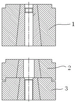
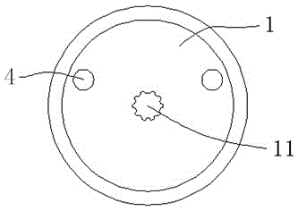
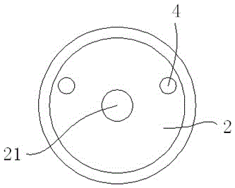
[0017] A cold extrusion die for an external spline shaft, comprising a coaxial upper die 1, a middle die 2 and a lower die 3, the upper die 1 is installed on the upper working platform of a hydraulic press, the middle die 2 and the lower die 3 Installed on the lower working platform of the hydraulic press; positioning pins 4 are installed through the upper mold 1, the middle mold 2 and the lower mold 3; the center of the upper mold 1 is the upper mold cavity 11, and the middle mold 2 center is the middle mold cavity 21, the center of the lower mold 3 is the lower mold cavity 31, and the center points of the upper mold cavity 11, the middle mold ca...


PUM


Abstract

The invention discloses an external spline shaft cold extrusion mold which comprises an upper mold, a middle mold and a lower mold which are coaxial. The upper mold is installed on an upper working platform of an oil press. The middle mold and the lower mold are installed on a lower working platform of the oil press. A positioning pin is installed in the middle mold and the lower mold in a penetrating manner. The center of the upper mold is an upper mold cavity. The center of the middle mold is a middle mold cavity. The center of the lower mold is a lower mold cavity. The central points of the upper mold cavity, the middle mold cavity and the lower mold cavity are located on the same central axis. By applying the external spline shaft cold extrusion mold, the problem of material flow uniformity caused by extrusion of a special-shaped irregular spline can be solved.

Description

technical field [0001] The invention relates to the field of molds, in particular to a cold extrusion mold. Background technique [0002] Driven by the general trend of energy saving and emission reduction, it has become an inevitable trend to develop from the original automobile hydraulic steering (3% energy consumption) to electric steering (0% energy consumption). The automobile electric steering system has a core part, the middle steering shaft, which is characterized by asymmetrical splines at both ends of the shaft. Processing asymmetrical splined shafts is a difficult problem in the machinery industry, and asymmetrical splines cannot be machined. . In the prior art, after the machining process is completed, it is necessary to take out the machined parts and then put in a new blank. During this period, man-hours are wasted, the efficiency is relatively low, and energy is wasted. Contents of the invention [0003] The technical problem mainly solved by the invention...

Claims


Application Information

Patent Timeline
Patent Type & Authority Applications(China)
IPC IPC(8): B21C25/02
Inventor 蒋浩
Owner 常熟市金华机械股份有限公司
Why Eureka
Try Eureka