
Running detecting system and method for conveyer belt glue peeling device

A technology of operation detection and conveyor belt, which is applied in the direction of conveyor control device, conveyor objects, transportation and packaging, etc. It can solve the problems that the rotating roller cannot run normally, the fault cannot be detected, and the motor runs normally, etc., and achieves simple structure, Loss prevention and low cost effects

Active Publication Date: 2015-11-04
QINGDAO MESNAC ELECTROMECHANICAL ENG +1
View PDF4 Cites 3 Cited by
  • Summary
  • Abstract
  • Description
  • Claims
  • Application Information

AI Technical Summary

Problems solved by technology

In the prior art, when the rotating roller of the stripping device is driven by a motor, the motor speed is mainly detected through electrical control, and whether the peeling device is in a normal working state is judged according to the speed of the motor, and the distance between the driving motor and the rotating roller is The transmission of power requires the transition of the transmission device, such as belt transmission, chain transmission, direct connection of coupling, etc. Therefore, no matter what transmission mode is used, if the intermediate transmission link fails, the motor may run normally but the rotating roller may not operate normally. , at this time the function of the glue brushing device has failed and the technology cannot detect the fault

Method used


Image

  • Running detecting system and method for conveyer belt glue peeling device
  • Running detecting system and method for conveyer belt glue peeling device
  • Running detecting system and method for conveyer belt glue peeling device

Examples


Embodiment 1

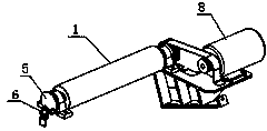
[0030] Embodiment one, refer to figure 2 and image 3 , this embodiment proposes a conveyor belt stripping device operation detection system, including a main processor, a signal plate 5 and a detection switch 6, the rotating roller 1 is fixed on the frame or other components through the bearing 7, and the driving device 8 is driven by a belt The rotary roller 1 rotates.

[0031] The signal disc 5 is installed at the end of the rotating roller 1. The signal disc 5 in this embodiment is circular, and there is a section of arc-shaped hole 5-1 at the edge of the signal disc 5. When rotating, the detection switch 6 or is facing the arc. shaped hole or facing other areas. Of course, the signal disc in this embodiment is not limited to a circle, and square, strip, semicircle or other irregular shapes may also be used.

[0032] The detection switch 6 is facing the signal disc 5 to detect the rotation signal of the detection signal disc 5 and output it to the main processor, and ...

Embodiment 2

[0036] Embodiment 2. In this embodiment, when the signal disc rotates, the alternate signal is not generated by detecting the through-hole area, but an object that can provide an alternate signal when it rotates is installed on the signal disc, such as installing a magnet on the signal disc. And use a magnetic detection switch to detect the rotation signal, such as Image 6 As shown, the detection switch is a magnetic switch, and the magnet 5-2 facing the proximity switch when rotating is installed on the signal disc 5 . Other principles are similar to Embodiment 1, and will not be repeated here.

Embodiment 3

[0037] Embodiment 3, this embodiment proposes a method for detecting the operation of a conveyor belt stripping device, including the following steps:

[0038] Step A, obtaining the rotation speed of the rotating roller through the signal disc installed on the rotating roller and the detection switch installed on the frame to detect the signal disc signal;

[0039] Step B. Comparing the rotational speed obtained in step A with the preset rotational speed to determine the operating status of the belt stripping device, and triggering an alarm when the stripping device is in a faulty state.

[0040] Step C, displaying the operating status of the stripping device through the display screen.

[0041] Of course, triggering the alarm and step C can also be selected in actual application.

[0042] The detection method of this embodiment is to directly detect the rotating roller itself, which avoids false detection and misjudgment caused by the detection of the driving device, and can...


PUM


Abstract

The invention provides a running detecting system and method for a conveyer belt glue peeling device. The running detecting system comprises a main processor, a rotation roller, a signal disc and a detecting switch; the rotation roller is installed on a rack; the signal disc is installed at the end of the rotation roller; and the detecting switch right faces the signal disc to be used for detecting a rotation signal of the signal disc and outputting the rotation signal to the main processor. The main processor judges the running state of the glue peeling device according to the rotation signal. According to the detecting scheme, the rotation roller is detected directly, faults can still be detected accurately under the conditions that a motor runs normally and a transmission device breaks down, it is guaranteed that the running state of the glue peeling device is accurately fed back in time, and losses caused by the faults of the glue peeling device in the production process are effectively prevented.

Description

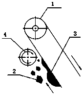
technical field [0001] The invention belongs to the field of rubber machinery, and in particular relates to an operation detection system of a conveyor belt stripping device. Background technique [0002] The stripping device is a device used in rubber processing equipment to remove the rubber sticking to the moving or stationary devices such as rollers, conveyor belts, and racks. The main structure of the device is usually a rotating roller. The rotary motion of the rotary rollers cleans the rubber material from the structures. [0003] Such as figure 1 As shown, taking a section of conveyor belt on a rubber mixing device as an example, the rubber sticks to the conveyor belt and moves to the upper left with the conveyor belt (the arrow in the figure shows the direction of movement of the conveyor belt), and the rotation direction of the stripping device Opposite to the movement direction of the rubber material, the rubber material is swept off when it touches the rotating...

Claims


Application Information

Patent Timeline
Patent Type & Authority Applications(China)
IPC IPC(8): B65G43/00
Inventor 官炳政柳伟华赵建王斌寻红涛李渊维
Owner QINGDAO MESNAC ELECTROMECHANICAL ENG
Learn More