Cross beam supporting system used for tower crane

A technology of support system and beam, applied in cranes, transportation and packaging, etc., can solve the problems of poor stability, occupying a lot of steel for the structure, restricting the load of tower cranes, etc., to achieve the effect of firm support

Active Publication Date: 2015-11-04
浙江兆弟技术有限公司
View PDF7 Cites 3 Cited by
  • Summary
  • Abstract
  • Description
  • Claims
  • Application Information

AI Technical Summary

Problems solved by technology

Wheel-type, car-type and crawler-type tower cranes have no track device, which is convenient to move, but cannot walk with a load and has poor stability
[0004] Fixed tower cranes are divided into two types: attached self-elevating type and internal climbing type according to different installation locations. The attached self-elevating tower crane can rise with the rise of the building, which is suitable for high-rise buildings. It bears the horizontal load transmitted by the tower crane and is easy to attach, but it takes up a lot of steel for the structure; the internal climbing tower crane climbs in the elevator shaft and stairwell inside the building with the help of a set of brackets and a lifting system. The jacking is more cumbersome, but Less steel is used for the occupied structure, no foundation is required, and all self-weight and loads are borne by the building
[0005] Whether it is a mobile tower crane or a fixed tower crane, either rely on the bottom of the tower crane to be fixed to the ground to achieve load bearing, or the building completes the load bearing, so the stability needs to be improved, and because of this, the increase in the load capacity of the tower crane is restricted

Method used


Image

  • Cross beam supporting system used for tower crane
  • Cross beam supporting system used for tower crane
  • Cross beam supporting system used for tower crane

Examples


Embodiment 1

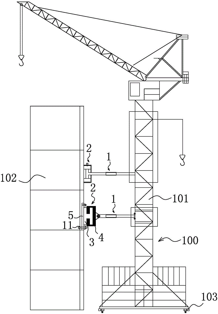
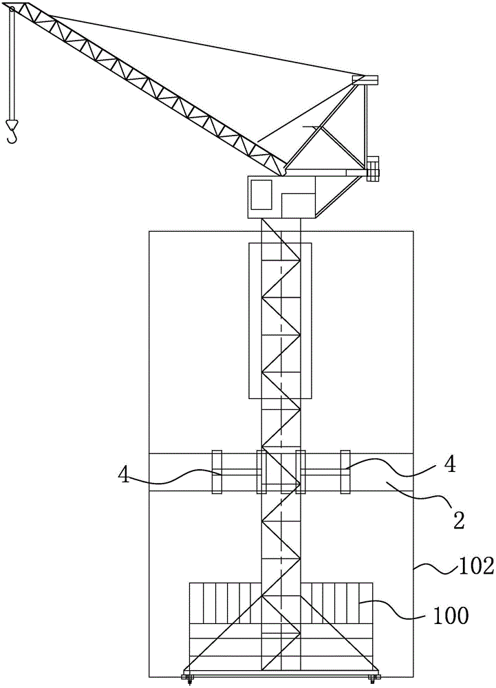
[0037] Such as figure 1 and figure 2 As shown, a beam support system for a tower crane includes a beam 1, the beam 1 is horizontally arranged and one end is fixedly connected to the tower body 101 of the tower crane 100, the tower body 101 is vertically arranged, and the other end of the beam 1 is connected to the slide rail The assembly 2 is connected, and the slide rail assembly 2 includes a slide rail 3 and a slider 4 that is compatible with the slide rail 3 and can walk along the slide rail 3. The cross section of the slide rail 3 is C-shaped or H-shaped. The sliding rail 3 is fixedly connected to the building 102, and the sliding block 4 is connected to the end of the beam 1.

[0038] The working principle of the present invention is: the beam 1 is connected with the slide rail assembly 2, the slide rail assembly 2 is fixed on the building 102, the tower crane 100 is supported by the beam 1, and the beam 1 is supported by the slide rail assembly 2 and the building 102, ...

Embodiment 2

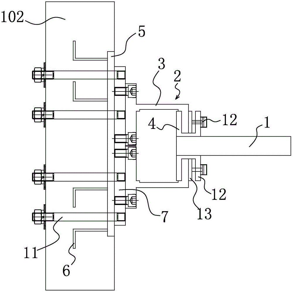
[0045] The structure and working principle of this embodiment are basically the same as that of Embodiment 1, the difference is that, as Figure 7 As shown, the slide rail 3 is H-shaped, including a first panel 8, a transverse support plate 9 and a second panel 10 connected to each other, the first panel 8 and the second panel 10 are parallel to each other, and the two ends of the transverse support plate 9 are respectively connected to the first One panel 8 is fixedly connected to the second panel 10, the first panel 8 is fixedly connected to the embedded plate 5, the second panel 10 is fixed with a slider brake cylinder 12, and the slider brake cylinder 12 is connected to the brake pad 13 and made The movable piece 13 is located between the second panel 10 and the slider 4 .

[0046] This embodiment provides a detachable structure of the slide rail assembly 2, which is convenient for installation and transportation during construction.

[0047] Such as Figure 8 and Figu...

Embodiment 3

[0049] The structure and working principle of this embodiment are basically the same as that of Embodiment 1, the difference is that, as Figure 5 , Figure 13 and Figure 14 As shown, the crossbeam 1 is provided with an axial distance adjustment mechanism 14 capable of adjusting the length of the crossbeam 1. The crossbeam 1 includes a front arm 15 and a rear arm 16, and a sleeve 17 is sleeved on the front arm 15 and the rear arm 16 and The tubes 17 are detachably fixedly connected to the front arm 15 and the rear arm 16 respectively.

[0050] When the tower crane 100 is walking, the distance between the tower crane 100 and the slide rail assembly 2 will change, but the length of the beam 1 is fixed. Therefore, if the length of the beam 1 cannot be adjusted, the distance between the tower crane 100 and the slide rail assembly 2 will be The clamping phenomenon occurs, causing the tower crane 100 to not be able to walk normally. Therefore, this embodiment designs an axial dis...


PUM


Abstract

The invention belongs to the technical field of buildings and relates to a cross beam supporting system used for a tower crane. The technical problems that in the prior art, the structure is unstable and the load capacity is small are solved. The cross beam supporting system used for the tower crane comprises a cross beam; the cross beam is horizontally arranged; one end of the cross beam is fixedly connected with the tower crane; the other end of the cross beam is connected with a sliding rail assembly; the sliding rail assembly comprises a sliding rail and a sliding block which is matched with the sliding rail and can walk along the sliding rail; the sliding rail is fixedly connected with a building; the sliding block is connected with the end of the cross beam. The cross beam supporting system used for the tower crane can be used for improving the load capacity and stability of the tower crane and make the tower crane to walk with loads.

Description

technical field [0001] The invention belongs to the technical field of construction engineering and relates to a rail support system for a tower crane. Background technique [0002] Tower crane is the most commonly used lifting equipment on construction sites, also known as "tower crane". Raw materials for construction. Tower crane is an indispensable equipment on the construction site. [0003] Tower cranes can be divided into mobile tower cranes and fixed tower cranes. Mobile tower cranes can be divided into four types: track type, tire type, car type, and crawler type according to different traveling devices. The track-type tower crane is fixed on the walking chassis and can run on a specially designed track. It has good stability and high work efficiency, so it is widely used in construction and installation projects. Tire-type, car-type and crawler-type tower cranes have no track device and are easy to move, but they cannot walk with a load and have poor stability. ...

Claims


Application Information

Patent Timeline
IPC IPC(8): B66C23/78B66C23/62
CPCB66C23/20B66C23/26B66C23/62B66C23/78B66C2700/03
Inventor 周兆弟
Owner 浙江兆弟技术有限公司
Why Eureka
Try Eureka