A simple lifting platform

A lifting platform, simple technology, applied in the direction of lifting frame, lifting device, etc., can solve the problems of poor heat treatment quality, workpiece drop, inconvenient use, etc., and achieve the effect of stable and reliable lifting movement, easy disassembly and maintenance, and convenient and reliable use

Inactive Publication Date: 2017-08-25
NFC (SHENYANG) METALLURGICAL MACHINERY CO LTD
View PDF1 Cites 0 Cited by
  • Summary
  • Abstract
  • Description
  • Claims
  • Application Information

AI Technical Summary

Problems solved by technology

It is necessary to manually turn the screw nut to realize the lifting of the workpiece, and the lateral movement of the workpiece cannot be realized
Inconvenient to use, resulting in poor product heat treatment quality
[0003] In addition, due to the direct connection between the screw nut and the stage, the heat-treated workpiece is usually heavy, which causes the screw to be subjected to a large radial force, which seriously affects the service life of the screw
However, if the weight of the workpiece to be heat treated is too large, the ordinary lifting mechanism cannot be used.
[0004] There are also some lifting platforms in other fields. For example, the patent number is 201010131872.3, and the name is the invention patent of "lifting platform", which provides a lifting platform for lifting goods in stores. This lifting platform cannot realize the lateral movement of workpieces. , In addition, the structure of this lifting platform is unreasonable. It realizes the movement of the lifting platform through the cooperation of the gear and the rack. The teeth of the gear and the rack are the main stress-bearing parts. If the workpiece is heavy, the teeth may break, causing the workpiece to be damaged. fall, dangerous

Method used


Image

  • A simple lifting platform
  • A simple lifting platform
  • A simple lifting platform

Examples


Embodiment Construction

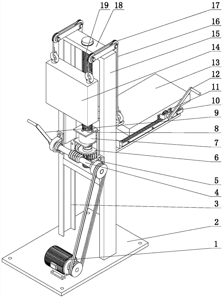
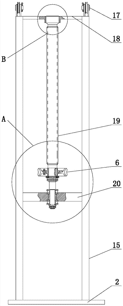
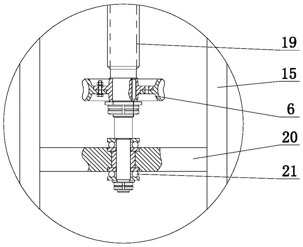
[0020] The present invention comprises base 2, and base 2 is provided with two trough-shaped columns 15, and crossbeam 18 is arranged between the top of two trough-shaped columns 15, is characterized in that: the groove 3 of described two trough-shaped columns 15 is oppositely arranged, and groove All be provided with the slide block 22 that cooperates with groove 3 in the groove 3 of shaped column 15; Described slide block 22 links to each other with the vertical edge 27 of the lifting frame 28 of same L shape; Described beam 18 below is provided with leading screw 19 , the lead screw 19 is provided with a screw nut 7, the screw nut 7 is provided with a connecting frame 8, and the vertical edge 27 of the L-shaped lifting frame 28 is provided with a connecting groove 26 matched with the connecting frame 8 ; The horizontal edge 29 of the lifting frame 28 is provided with a horizontal slide plate 13, and the horizontal sliding plate 13 is provided with a rotating gear 11; .

[...


PUM


Abstract

A simple lifting platform belongs to the technical field of product heat treatment platforms, and in particular relates to a simple lifting platform for product heat treatment. The invention provides a simple lifting platform which is simple in structure, stable and reliable, and can realize vertical and lateral movement. The invention includes a base, on which two groove-shaped columns are arranged, and a crossbeam is arranged between the top ends of the two groove-shaped columns. A slider matching the groove is provided; the slider is connected to the vertical side of the same L-shaped lifting frame; a lead screw is arranged under the beam, and a screw nut is arranged on the lead screw, and a connecting screw is arranged on the screw nut. frame, the vertical side of the L-shaped lifting frame is provided with a connecting groove that matches the connecting frame; the horizontal side of the lifting frame is provided with a horizontal slide plate, and the horizontal slide plate is provided with a rotating gear; the lifting frame A toothed rack cooperating with the rotating gear is arranged on the horizontal side of the frame.

Description

technical field [0001] The invention belongs to the technical field of product heat treatment platforms, and in particular relates to a simple lifting platform for product heat treatment. Background technique [0002] Some product parts require the workpiece to move up and down at a constant and low speed during the heat treatment process. The existing lifting mechanism for heat treatment of the workpiece usually uses a simple screw nut mechanism. It is necessary to manually turn the screw nut to realize the lifting of the workpiece, and the lateral movement of the workpiece cannot be realized. Inconvenient to use, resulting in poor product heat treatment quality. [0003] In addition, since the screw nut is directly connected to the stage, and the heat-treated workpiece is usually heavy in weight, this causes the screw to be subjected to a large radial force, which seriously affects the service life of the screw. And if the workpiece that needs heat treatment is too heavy...

Claims


Application Information

Patent Timeline
Patent Type & Authority Patents(China)
IPC IPC(8): B66F7/14B66F7/28
CPCB66F7/14B66F7/28B66F2700/00
Inventor 梁军卢兰英于晓红张晓阳张毅
Owner NFC (SHENYANG) METALLURGICAL MACHINERY CO LTD
Why Eureka
Try Eureka