Intermittent pressure flow drainage system

A drainage system and pressure flow technology, applied in the field of innovation and invention, can solve the problems of inability to achieve pressure flow drainage, irregular drainage, and flow interruption.

Inactive Publication Date: 2015-11-04
XIAMEN CITY YIJING ENVIRONMENT ENG CO LTD
View PDF4 Cites 7 Cited by
  • Summary
  • Abstract
  • Description
  • Claims
  • Application Information

AI Technical Summary

Problems solved by technology

The reason why the pressure flow is not used is often due to the irregularity of the drainage, and the flow is often interrupted during the drainage process, so it is impossible to achieve continuous or short-term continuous pressure flow drainage

Method used


Image

  • Intermittent pressure flow drainage system
  • Intermittent pressure flow drainage system
  • Intermittent pressure flow drainage system

Examples


specific Embodiment 1

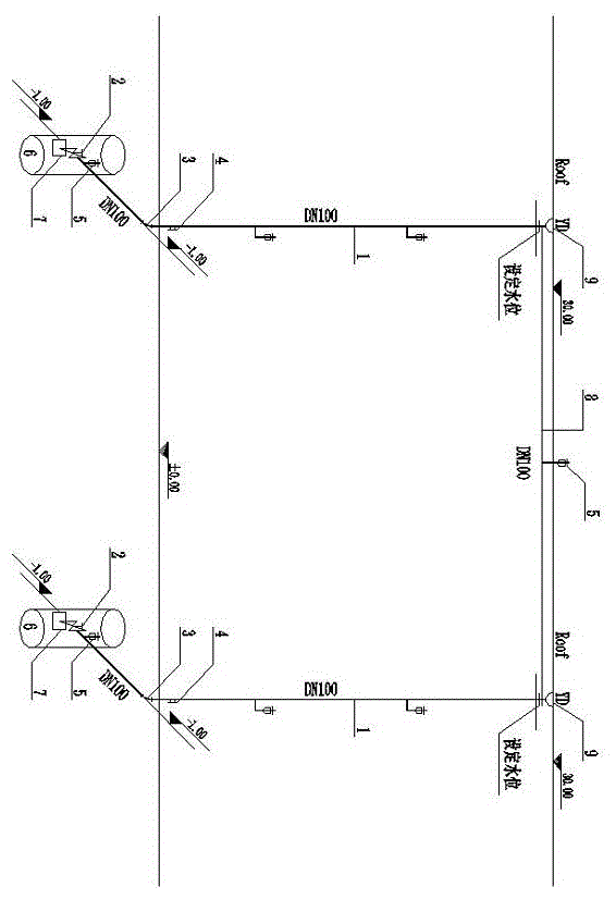
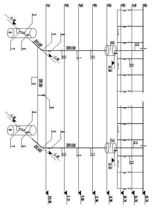
[0077] The specific resistance of the steel pipe adopted in the specific embodiment one is 267.4, the length of a single system pipe is 35 meters, and the water level difference between inlet and outlet is set to be 30 meters, so Q=(30 / 267.4*35) 1 / 2 =0.0566 (cubic meter / second), that is, 56.6 liters / second. This flow rate is the maximum flow rate of the system, and it is also the design flow rate of a single system, which meets the rainwater discharge requirements, and the corresponding flow rate is 7.22 m / s. The average flow rate is 28.3 liters / second and the average flow rate is 3.61 m / s, which meets the requirement of metal pipes with a flow rate of less than 10 m / s. In view of the fact that the average flow rate is much greater than the economic flow rate, it may be considered to add a small hydroelectric generator in the inspection well as an energy dissipation measure. Because the rainwater has few impurities, it is also conceivable to set up a micro-hydraulic generator...


PUM


Abstract

Core elements of an intermittent pressure flow drainage system are: pressure pipelines 1, set pressure drain valves 2 and automatic exhaust valves 5. First, the intermittent pressure flow drainage system collects waste water so that water level rises and energy is stored. No water is drained but air is released during the whole stage of collecting water. The set pressure drain valve opens automatically when the water level rises to a set pressure. Then the system enters into a pressure drainage stage when the flow is quickly discharged in a variable head pressure flow way. According to this system, pressure drainage is realized by use of gravitational potential energy of a flow without additional power device. The system has following beneficial effects: saving tubular product; reducing cost; generating electricity in some cases. Because of high flow velocity, water pipelines will not be blocked or clogged. The drainage system is energy-saving.

Description

technical field [0001] The invention is an innovative invention of a fluid transmission system in the water supply and drainage industry. Background technique [0002] At present, conventional drainage systems are generally intermittent non-pressurized gravity flow systems. The reason why pressure flow is not used is often due to the irregularity of drainage, and the flow is often interrupted during the drainage process, so continuous or short-term continuous pressure flow drainage cannot be realized. The drainage pipes designed according to the non-pressure gravity flow system are generally designed according to the non-full flow. In addition, some sewage and wastewater have more impurities and are larger. Compared with the pressure flow, the gravity flow drainage pipes are often much larger in diameter and quantity. a lot. This phenomenon is particularly evident in building drainage systems. There are often dozens or even hundreds of drainage pipes at the bottom of a bu...

Claims


Application Information

Patent Timeline
IPC IPC(8): E03F1/00E03F3/04
CPCE03F1/00
Inventor 涂程光
Owner XIAMEN CITY YIJING ENVIRONMENT ENG CO LTD
Why Eureka
Try Eureka