Boiler flue gas waste heat water tank

A boiler flue gas and water tank technology, applied in the direction of preheating, feed water heater, heat exchanger type, etc., can solve the problems of high temperature waste heat utilization, steam temperature fluctuation, steam temperature drop, etc., to achieve simple structure, energy saving and reduction Consumption effect, low cost effect

Inactive Publication Date: 2015-11-04
余志斌
5 Cites 2 Cited by

AI-Extracted Technical Summary

Problems solved by technology

[0002] When heating the boiler with fuel, flue gas will be generated. According to calculations, the temperature of the flue gas is usually as low as 160°C. Existing boilers often directly discharge this high-temperature flue gas into the air without reducing the high temperature. Waste heat is used to cause waste; on the other hand, when replenishing wat...

Method used

During use, boiler flue gas enters air intake cavity 1 from upper air inlet 13, enters flue gas channel 4 of bottom by heat dissipation ventilation pipe 5, enters air outlet cavity 2 of top by heat dissipation ventilation pipe 5 again from air outlet 14 discharge. During this process, the water in the water tank 3 absorbs the heat of the heat dissipation ventilation pipe 5, is heated from normal temperature to about 90°C, and then is added into the water ...

Abstract

The invention discloses a boiler flue gas waste heat water tank. The boiler flue gas waste heat water tank is characterized by comprising a shell; an inner cavity of the shell is divided into an upper portion, a middle portion and a lower portion; the upper portion is divided into a gas inlet cavity and a gas outlet cavity; the middle portion is a water tank, and the lower portion is an flue gas channel; the water tank is internally provided with a plurality of heat dissipation ventilation pipelines, and the gas inlet cavity and the gas outlet cavity of the upper portion are communicated with the flue gas channel of the lower portion through the heat dissipation ventilation pipelines; a water inlet is arranged at the upper portion of the water tank, and a water outlet is arranged at the lower portion of the water tank; exhaust openings are arranged at the upper end of the water tank; an ash discharging opening is arranged on the wall of the flue gas channel of the lower portion of the inner cavity of the shell; and the water tank is provided with a liquid level gauge and a thermometer. Normal temperature water in the water tank is heated by means of flue gas waste heat of a boiler; the flue gas waste heat is utilized, fuel is saved as well; meanwhile, steam temperature fluctuations are reduced; and the water tank is simple in structure, low in cost and high in flue gas waste heat utilization rate and good in energy-saving and consumption-reducing effect.

Application Domain

Stationary conduit assembliesFeed-water heaters

Technology Topic

Process engineeringThermometer +5

Image

  • Boiler flue gas waste heat water tank

Examples

  • Experimental program(1)

Example Embodiment

[0015] Examples:
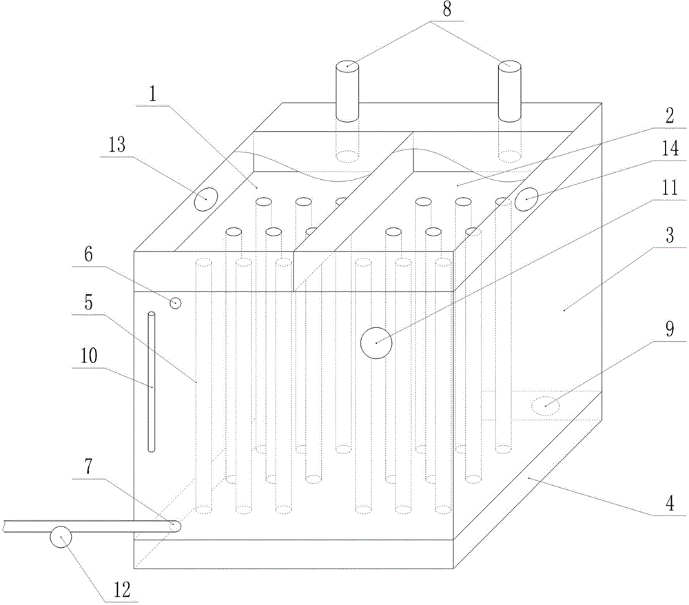
[0016] Reference figure 1 , A boiler flue gas residual hot water tank, comprising a shell, the inner cavity of the shell is divided into upper, middle and lower parts, wherein the upper part is divided into an air inlet cavity 1 and an air outlet cavity 2, the middle part is a water tank 3, and the lower part The flue gas channel 4 is provided with a plurality of heat dissipation vent pipes 5 in the water tank 3, and the upper air inlet cavity 1 and the outlet cavity 2 are communicated with the lower flue gas channel 4 through the heat dissipation vent pipe 5;
[0017] The upper part of the water tank 3 is provided with a water inlet 6 and the lower part is provided with a water outlet 7; the upper end of the water tank 3 is provided with an exhaust port 8;
[0018] The wall of the flue gas channel 4 at the lower part of the inner cavity of the casing is provided with an ash discharge port 9.
[0019] The water tank 3 is provided with a level gauge 10, the water level of the water tank can be observed through the level gauge 10 to determine whether water needs to be added, or the level gauge 10 can be connected to an automatic water inlet device to realize automatic control of water inflow.
[0020] The water tank 3 is provided with a thermometer 11, so that the water temperature in the water tank 3 can be understood intuitively.
[0021] The water outlet 7 of the water tank 3 communicates with the water inlet of the boiler through a water pipe, and a water pump 12 is provided on the water pipe. When it is necessary to add water to the water chamber of the boiler, just turn on the water pump 12.
[0022] When in use, boiler flue gas enters the intake cavity 1 from the upper air inlet 13, enters the lower flue gas channel 4 through the heat dissipation air duct 5, and then enters the upper air outlet cavity 2 through the heat dissipation air duct 5 and is discharged from the air outlet 14. In this process, the water in the water tank 3 absorbs the heat of the heat dissipation vent pipe 5, is heated from room temperature to about 90°C, and then is added to the water cavity of the boiler through the water pump 12, which not only uses the flue gas waste heat, but also saves fuel At the same time, the temperature fluctuation of the steam is also reduced; in addition, the flue gas channel 4 is arranged in the lower part, which facilitates the deposition of smoke and dust in the flue gas channel 4, which is convenient for cleaning, and at the same time, it has a better effect on reducing the emission of smoke and dust.

PUM

no PUM

Description & Claims & Application Information

We can also present the details of the Description, Claims and Application information to help users get a comprehensive understanding of the technical details of the patent, such as background art, summary of invention, brief description of drawings, description of embodiments, and other original content. On the other hand, users can also determine the specific scope of protection of the technology through the list of claims; as well as understand the changes in the life cycle of the technology with the presentation of the patent timeline. Login to view more.

Similar technology patents

Hydraulic combined engine

InactiveCN105020111ASave the driving forcesave fuel
Owner:王守玉

Classification and recommendation of technical efficacy words

  • save fuel
  • small temperature fluctuations

Refrigerator frequency conversion control method and application thereof

ActiveCN103776234AReduce start-up and shutdown lossessmall temperature fluctuations
Owner:CHANGHONG MEILING CO LTD

Refrigerator and control method thereof

ActiveCN105987560Aflexible controlsmall temperature fluctuations
Owner:QINGDAO HAIER SMART TECH R & D CO LTD +1

Air conditioning device

ActiveCN109642747Aavoid flyingsmall temperature fluctuations
Owner:MITSUBISHI ELECTRIC CORP

Combustion method of low-concentration combustible gas and fluidized reactor

InactiveCN101713534Asmall temperature fluctuationsIncreased chance of fire
Owner:CHONGQING UNIV

Heat management module of engine cooling system and engine cooling system

InactiveCN111365113Asmall temperature fluctuationsReduce thermal shock
Owner:CHONGQING CHANGAN AUTOMOBILE CO LTD
Why Eureka
Try Eureka