Supercharge Your Innovation With Domain-Expert AI Agents!

A programmable resistance calibrator

A technology of calibrator and resistance, which is applied in the direction of instruments, electrical components, and measuring electrical variables, etc., can solve the problems of high relay noise, affecting output accuracy, and low detection efficiency, so as to achieve long service life of equipment, improve production efficiency, and improve equipment quality. The effect of low cost

Active Publication Date: 2017-10-24
HUIZHOU DESAY SV AUTOMOTIVE
View PDF5 Cites 0 Cited by
  • Summary
  • Abstract
  • Description
  • Claims
  • Application Information

AI Technical Summary

Problems solved by technology

The biggest disadvantage of this is: 1. The inspector needs to intervene in the measurement process, and the subjective factors of the inspector will be introduced in the output process of the resistance signal, which may cause inspection errors; 2. On the other hand, although the tested product can pass Bus or display device to indicate the measured resistance signal, but because the change of the resistance signal requires manual adjustment, the detection process has a low degree of automation, which is not conducive to the automation of product inspection; 3. Mechanical contact resistance boxes and sliding rheostats, the use time After the length becomes longer, it will cause errors due to mechanical wear and affect the test results; 4. The detection efficiency is low; another commonly used resistance output method is to use the relay array program to output the resistance value within a certain range
Although the automatic control of the resistance output can be realized in this way, there are also disadvantages: 1. The noise is large when the relay is turned on and off; 2. The contact resistance of the relay contacts increases with the use time, which affects the output accuracy; Subdivision, it is difficult to achieve continuous stepless adjustment, and the resolution is at the Ω level; 4. The system cost is very high

Method used


Image

  • A programmable resistance calibrator
  • A programmable resistance calibrator
  • A programmable resistance calibrator

Examples


Embodiment Construction

[0020] The programmable resistance calibrator of the present invention will be further described in detail below in conjunction with specific embodiments and accompanying drawings.

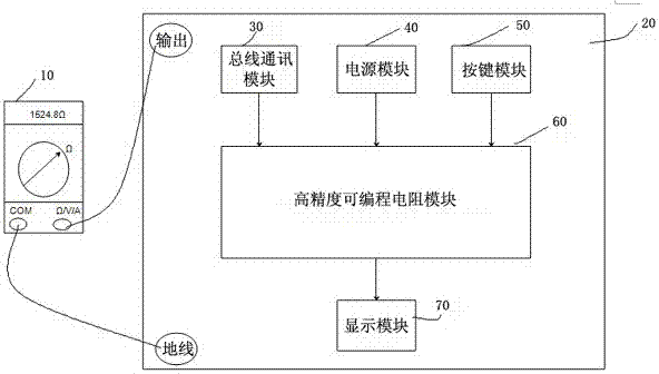
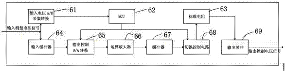
[0021] See figure 1 , a programmable resistance calibrator, which includes a system host and a product to be tested 10 connected to its circuit, wherein the system host includes a high-precision programmable resistance module 60, the output terminal of the programmable resistance module 60 is connected to a display module 70, and its input terminals are respectively connected to the bus communication module 30, the power supply module 40 and the key module 50, the system host receives commands through the communication module 30 or the key module 40, and outputs the set resistance value through the operation and processing of the programmable resistance module 60 to the outside.

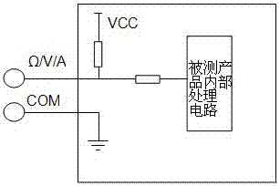
[0022] In this embodiment, the product 10 to be tested is the Ω measurement gear of the multimeter, which can accurat...


PUM


Abstract

The invention relates to a programmable resistance calibrator. It includes a system host and a product to be tested connected to its circuit. The system host includes a high-precision programmable resistance module. The output of the programmable resistance module is connected to a display module, and its input is respectively connected to the bus communication module and the power supply module. Connected with the key module, the system host receives commands through the communication module or the key module, and outputs the set resistance value to the outside through the operation and processing of the programmable resistance module. The programmable resistance calibrator of the present invention is a completely digital programmable resistance output mode, which has the following characteristics: the range of output resistance is continuous, the output range of off-line programming configuration resistance and the output of online real-time control resistance can be realized, with Common network communication interfaces such as CAN Bus, RS-485, and Ethernet are convenient for integration with existing automated test equipment; long-term use will not cause errors such as mechanical wear and tear, and the cost is low.

Description

technical field [0001] The invention relates to the technical field of electronic measurement, in particular to a high-precision non-polar programmable resistance calibrator. Background technique [0002] During the inspection process of the product, the measurement and detection of the resistance signal is generally to simulate the input of the external resistance signal through the sliding rheostat and the resistance box; to check the expected performance of the product under test according to the resistance value of the external known analog signal to inspect the product good or bad. The biggest disadvantage of this is: 1. The inspector needs to intervene in the measurement process, and the subjective factors of the inspector will be introduced in the output process of the resistance signal, which may cause inspection errors; 2. On the other hand, although the tested product can pass Bus or display device to indicate the measured resistance signal, but because the change...

Claims


Application Information

Patent Timeline
Patent Type & Authority Patents(China)
IPC IPC(8): G01R35/00H04L29/06
Inventor 孙志江钟声
Owner HUIZHOU DESAY SV AUTOMOTIVE
Features
  • R&D
  • Intellectual Property
  • Life Sciences
  • Materials
  • Tech Scout
  • Unparalleled Data Quality
  • Higher Quality Content
  • 60% Fewer Hallucinations
Learn More