Layered speed positioning method for regional rock microseismic source

A positioning method and area division technology, applied in the field of geotechnical engineering, can solve problems such as the limitation of seismic source positioning accuracy

Inactive Publication Date: 2015-11-04
SICHUAN UNIV
View PDF10 Cites 27 Cited by
  • Summary
  • Abstract
  • Description
  • Claims
  • Application Information

AI Technical Summary

Problems solved by technology

Therefore, the existing nonlinear positioning method locates the microseismic source on the basis of uniform and single rock mass wave velocity, which will inevitably be affected by the layering of the rock mass medium and on-site construction, and the accuracy of its source positioning will inevitably be limited.

Method used


Image

  • Layered speed positioning method for regional rock microseismic source
  • Layered speed positioning method for regional rock microseismic source
  • Layered speed positioning method for regional rock microseismic source

Examples


Embodiment

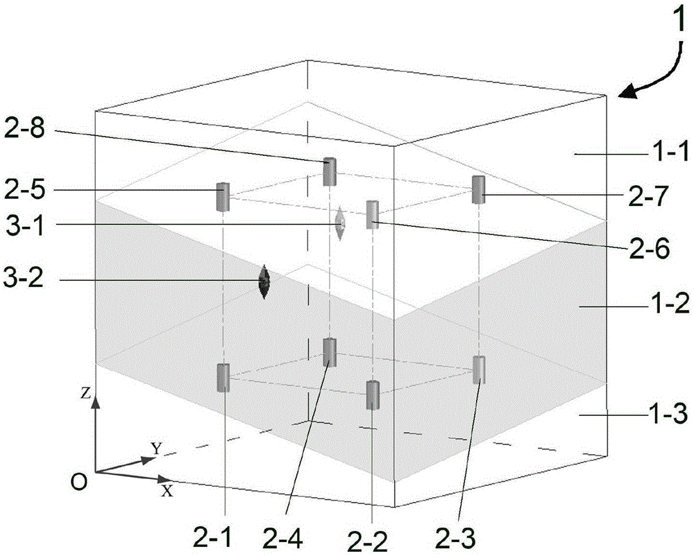
[0066] In this embodiment, the size of the rock mass area of ​​the microseismic source to be tested is 200m × 200m × 200m, and the positioning steps of the microseismic source are as follows:

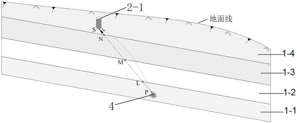
[0067] ①According to the rock mass wave velocity in the rock mass area of ​​the microseismic source to be tested recorded in the geological exploration data, the above rock mass area is divided into three wave velocity layers, the rock mass wave velocity in the same wave velocity layer is equal and the interface of each wave velocity layer In order to be parallel to each other, each wave velocity layer is recorded as the first wave velocity layer 1-1, the second wave velocity layer 1-2, and the third wave velocity layer 1-3 from the upper side to the lower side in the direction perpendicular to the wave velocity layer. The wave velocity of the rock mass in each layer is denoted as V 1 ,V 2 ,V 3 Set up a three-dimensional Cartesian coordinate system with the O point in the rock mass re...


PUM


Abstract

The invention belongs to the field of geotechnical engineering, and provides a layered speed positioning method for a regional rock microseismic source. The method comprises the following steps: (1), dividing the rock region of a to-be-detected seismic source into different wave velocity layers, building a three-dimensional rectangular coordinate system, and calculating an analytic equation of interfaces of all wave velocity layers; (2), installing sensors in the rock region, and measuring the spatial coordinates of all sensors; (3) carrying out an explosion test in the rock region, and calculating the wave velocities of all wave velocity layers; (4) calculating the spatial coordinates (x0, y0, z0) of the microseismic source. The method provided by the invention achieves high positioning precision of the microseismic source, and can prompt the technology of microseismic monitoring to play a good role in prediction and early warning in engineering practice.

Description

technical field [0001] The invention belongs to the field of geotechnical engineering, in particular to a layered velocity positioning method of regional rock microseismic sources. Background technique [0002] Under the action of external stress, local elastic-plastic energy concentration will occur inside the rock mass. When the energy accumulates to a certain critical value, it will cause the generation and expansion of micro-cracks in the rock mass. The generation and expansion of micro-cracks are accompanied by elastic wave Or the release of stress waves and rapid propagation in the surrounding rock mass, this elastic wave is called microseismic in geology. Microseismic monitoring technology is to collect microseismic signals by arranging sensors in the rock mass of the monitoring area, and analyze the collected signals to locate the microseismic source and delineate the damaged area of ​​the rock mass, providing an effective basis for the stability evaluation of the re...

Claims


Application Information

Patent Timeline
Patent Type & Authority Applications(China)
IPC IPC(8): G01S5/06
CPCG01S5/06
Inventor 戴峰郭亮徐奴文姜鹏李韬
Owner SICHUAN UNIV
Why Eureka
Try Eureka