Optical fiber fusion splicing method

An optical fiber fusion and optical fiber technology, applied in the field of optical fiber fusion, can solve the problems of increased production cost, easy loosening of optical fibers, and many consumables, etc., to achieve the effect of improving work efficiency, reducing production costs, and reducing workload

Active Publication Date: 2015-11-04
CHINA ERACOM CONTRACTING & ENG
View PDF6 Cites 3 Cited by
  • Summary
  • Abstract
  • Description
  • Claims
  • Application Information

AI Technical Summary

Problems solved by technology

When performing fusion splicing, it is necessary to remove the coating layer of the fusion splicing part. Since the optical fiber in the optical cable is easily loosened without the coating layer, it is difficult to align during fusion splicing, which affects the quality of the optical fiber obtained by fusion splicing.
Moreover, for a single optical fiber, it is necessary to use a single optical fiber fusion splicer for fusion splicing. When there are many optical fibers in the optical cable, it will take a long time for optical fiber fusion and consume more consumables, which will increase the production cost.

Method used


Image

  • Optical fiber fusion splicing method
  • Optical fiber fusion splicing method
  • Optical fiber fusion splicing method

Examples


Embodiment 1-12

[0023] A method for splicing optical fibers, comprising the steps of:

[0024] a. Removing the coating layer: using the thermal stripping method to remove the coating layer of the optical fibers in the fusion splicing area of ​​the two optical cables, and then cleaning the surface of the optical fibers, and there are at least two optical fibers in the optical cables;

[0025] b. Glue coating: glue the optical fibers stripped of the coating layer in the optical cable together to obtain an optical fiber bundle;

[0026] c. Cutting: After the glue on the optical fiber bundle obtained in step b is cured, cut the end face of the optical fiber bundle flat with a cutter;

[0027] d. Fusion splicing: Align the ends of the optical fiber bundles of the two optical cables, and place them in a fusion splicer for fusion splicing.

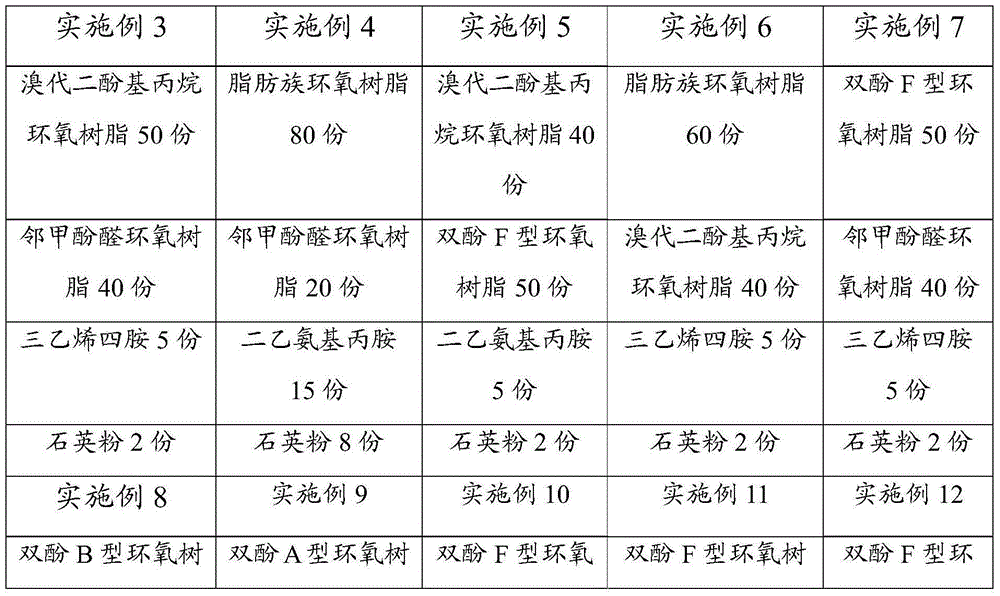
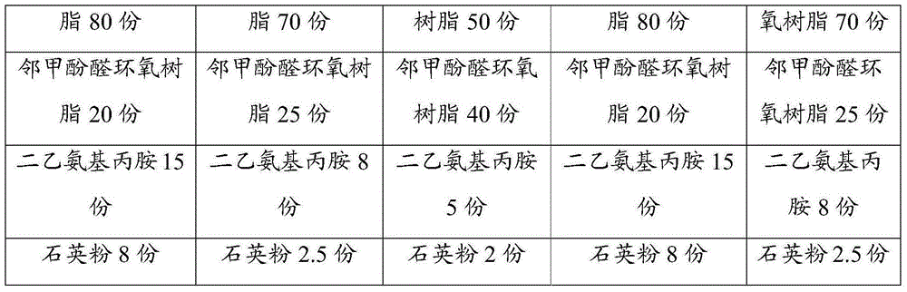
[0028] The optical fiber fusion splicing method of embodiment 1-6, its fusing method, step are identical, and difference is that the glue used is different; Wh...

experiment example

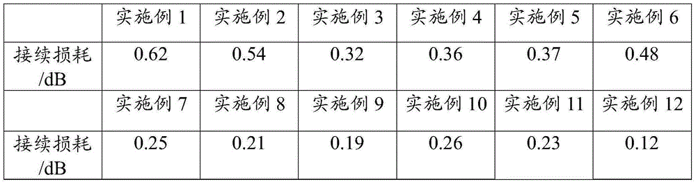
[0033] Use the method in GB / T 16529.3-1997 "Fiber Optic Cable Connectors Part 3: Substandard Fiber Optic Cable Fusion Splicing Connectors" to test the optical fibers obtained by fusion splicing in Examples 1-12. The test index is splicing loss, and the specific test results are detailed See Table 2 below:

[0034] Table 2: Splicing loss test data table of fusion splice fiber

[0035]

[0036] As can be seen from the data in the above table, the optical fiber fusion splicing method of the present invention has low fiber splicing loss, and does not need to weld the optical fibers one by one like the traditional process, which reduces the workload, improves the work efficiency, and reduces the production cost. . Wherein, by adopting the glue of the present invention, the influence of the glue on the quality of optical fiber fusion can be further reduced, and the amount of splicing loss can be reduced.


PUM


Abstract

The invention relates to an optical fiber fusion splicing method comprising the following steps that a. coating layers are removed: the coating layers of the optical fibers in two optical cables in a fusion splicing area are removed by adopting a hot stripping method, then cleaning processing is performed on the surfaces of the optical fibers, and there are at least two optical fibers in the optical cables; b. glue is coated: the optical fibers, of which the coating layers are stripped, in the optical cables are adhered together by glue so that optical fiber bundles are obtained; c. cutting is performed: after glue on the optical fiber bundles obtained through the step b is solidified, the end surfaces of the optical fiber bundles are cut to be flat by a cutting knife; and d. fusion splicing is performed: the end surfaces of the optical fiber bundles of the two optical cables are aligned and then arranged in a fusion splicing machine to perform fusion splicing. The optical fiber fusion splicing method has advantages of being high in efficiency and low in cost.

Description

technical field [0001] The invention relates to the field of optical fiber processing, in particular to an optical fiber fusion splicing method. Background technique [0002] In the construction of optical cables in communication engineering, thermal fusion splicing technology is required when the optical cables are terminated. Existing optical cables generally have multiple optical fibers in them. When performing fusion splicing, it is necessary to remove the coating layer of the fusion splicing part. Since the optical fiber in the optical cable is easily loose without the coating layer, it is difficult to align during fusion splicing, which affects the quality of the optical fiber obtained by fusion splicing. Moreover, for a single optical fiber, a single optical fiber fusion splicer needs to be used for fusion splicing. When there are many optical fibers in the optical cable, it takes a long time for optical fiber fusion and consumes a lot of consumables, which increases ...

Claims


Application Information

Patent Timeline
Patent Type & Authority Applications(China)
IPC IPC(8): G02B6/245G02B6/255
CPCG02B6/245G02B6/2553G02B6/2555
Inventor 任川
Owner CHINA ERACOM CONTRACTING & ENG
Why Eureka
Try Eureka