
Combine harvester

The technology of a combine harvester and a harvesting device is applied in the direction of harvesters, cutters, agricultural machinery and implements, etc., and can solve the unbalanced lifting force of the left and right ends of the second lawn mower and the tendency of the second lawn mower to move to the left and right Tilting and other issues can be improved to achieve the effect of improving maintenance workability and balancing lifting force

Inactive Publication Date: 2015-11-04
YANMAR CO LTD
View PDF6 Cites 7 Cited by
  • Summary
  • Abstract
  • Description
  • Claims
  • Application Information

AI Technical Summary

Problems solved by technology

Because the compression spring is arranged between the spring seat and the central frame connected between the front part of the traveling body and the axle box through the support bolt shaft, the lifting force of the left and right ends of the second lawnmower tends to become unbalanced. The problem that the 2nd lawn mower tends to tilt left and right

Method used


Image

  • Combine harvester
  • Combine harvester
  • Combine harvester

Examples


Embodiment Construction

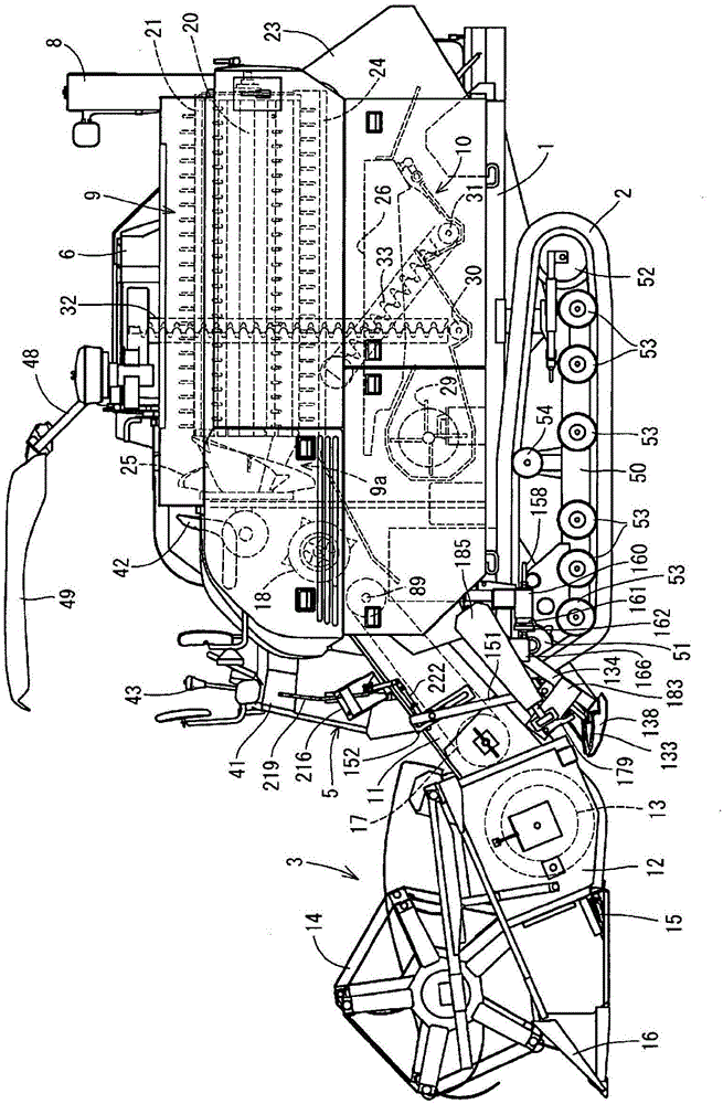
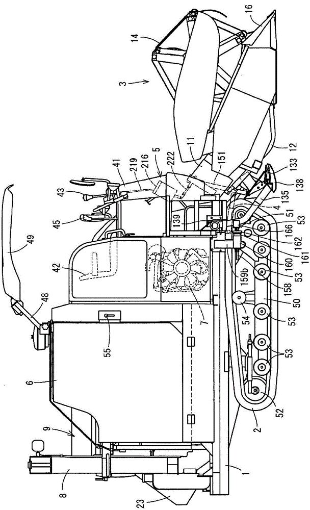
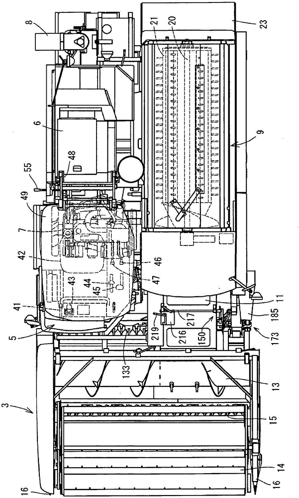
[0053] Below, based on the graph for a common type combine ( Figure 1 to Figure 4 ) to describe the embodiment of the present invention. figure 1 is the left side view of the combine harvester, figure 2 is the right side view of the combine harvester, image 3 is a top view of the combine harvester, Figure 4 It is the left perspective view of the combine harvester. First, refer to Figure 1 ~ Figure 3 The schematic structure of a combine harvester is demonstrated. In addition, in the following description, the left side when facing the advancing direction of the traveling body 1 is simply called the left side, and the right side when facing the advancing direction of the traveling body 1 is simply called the right side.

[0054] like Figure 1 ~ Figure 3 As shown, the common type combine harvester of embodiment is provided with the traveling body 1 supported by the right and left pair of crawlers 2 made of the rubber crawler which is a traveling part. On the front po...


PUM


Abstract

The present invention addresses the problem of providing a combine harvester with which maintenance-work properties of a mechanism for second cutting blades (133) can be improved while improving a floating function of the second cutting blades (133). This combine harvester is provided with: a reaping apparatus (3) provided with first cutting blades (15); a threshing apparatus (9) provided with a threshing cylinder (21); a traveling machine body (1) provided with an engine (7) and a driver seat (42); and second cutting blades (133) for severing residual culms in the first cutting blades (15), said second cutting blades (133) being fitted to the traveling machine body (1) via a left-side frame (134) and a right-side frame (135). Left and right floating support mechanisms (157) are provided to the traveling machine body (1). The left-and-right floating support mechanisms (157) are configured so as to respectively apply elastic pressure to the right-side frame (134) and the left-side frame (135).

Description

technical field [0001] The present invention relates to a combine harvester equipped with a harvesting device for reaping uncut straws in a field and a threshing device for threshing grains of harvested straws. Background technique [0002] As prior art, there are following technologies, that is, equipped with a traveling body, a harvesting device, a threshing device, a feeding bin, an engine, and a grain sorting mechanism; the traveling body has a walking part and a driver's seat; The threshing device has a threshing drum; the feeding bin supplies the harvested straw from the harvesting device to the threshing device; the engine drives each part; the grain sorting mechanism sorts the threshed objects of the threshing device; The second cutting knife continuously harvests the unharvested straw in the field, and cuts off the stubble of the first cutting knife; the height of the stubble in the field is adjusted by the second cutting knife to reduce the stubble remaining in the...

Claims


Application Information

Patent Timeline
Patent Type & Authority Applications(China)
IPC IPC(8): A01D67/00A01D34/24A01D41/02
CPCA01D41/14A01D41/06
Inventor 佐藤孝康犹原康裕
Owner YANMAR CO LTD
Learn More