
Intertidal zone floating reef

An intertidal zone and floating-based technology, applied in fish farming, application, climate change adaptation, etc., can solve the problems of inability to achieve fish gathering effects, inconvenient placement and setting of fish reefs and algae reefs, poor primary fish gathering effects, etc. problem, to achieve good protection effect, good fish gathering effect, and rich biological species

Inactive Publication Date: 2015-11-11
ZHEJIANG OCEAN UNIV
View PDF8 Cites 2 Cited by
  • Summary
  • Abstract
  • Description
  • Claims
  • Application Information

AI Technical Summary

Problems solved by technology

However, in the prior art, it is inconvenient to place and set fish reefs and algae reefs.
This is because most of the fish reefs need to sink to the bottom (sea bottom) or close to the bottom of the sea, but after the fish reefs are placed, the primary fish gathering effect is poor, and it is difficult to form a good micro-ecosystem on the bottom of the sea; algae reefs can provide more food for fish schools source, but because many seaweeds (especially artificially propagated seaweeds, such as sargassum and sargassum, etc.) grow relatively fast near the sea surface (intertidal zone, within tens of meters under the sea, etc.), on the seabed due to light exposure Poor and slow growth, so the algae reefs are usually placed closer to the sea surface, but it is difficult to provide good protection for fish schools near the sea surface, so the best fish gathering effect cannot be achieved

Method used


Image

  • Intertidal zone floating reef
  • Intertidal zone floating reef
  • Intertidal zone floating reef

Examples


Embodiment 1

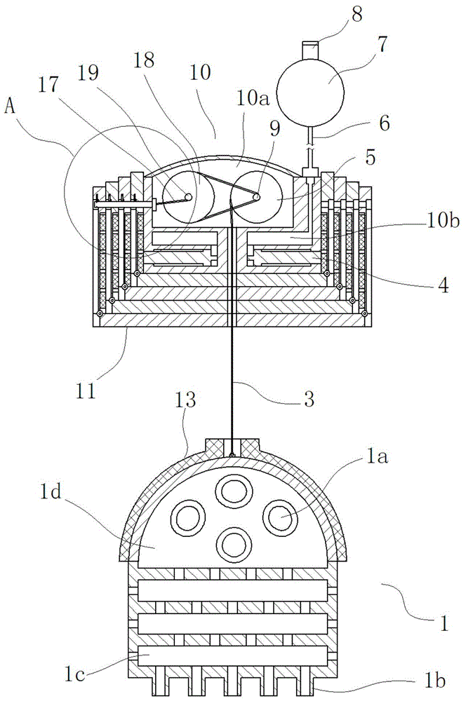
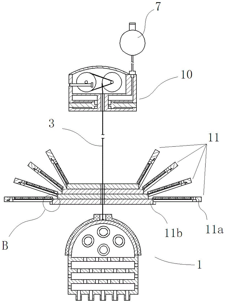
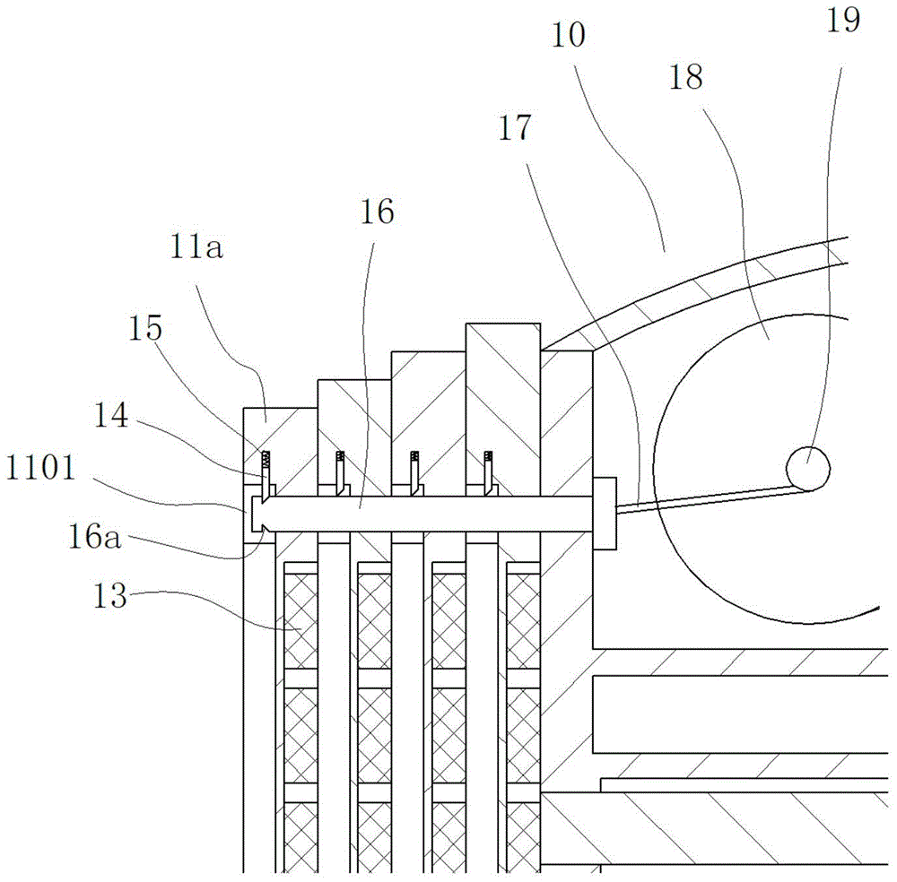
[0022] Embodiment 1: as figure 1 In the shown embodiment, a floating reef in the intertidal zone includes a floating base 10 and a submerged base 1, wherein the upper surface of the floating base is provided with shell fragments, and an isolated upper chamber 10a and a lower chamber 10b are provided in the floating base, The upper chamber is provided with a bobbin 5 for winding the rope 3, and four expansion bases 11 arranged in parallel in the vertical direction are arranged under the floating base, and a control expansion base and a floating base are arranged between the floating base and the expansion base. Separate disengagement mechanism. The sinking foundation and the floating foundation are connected by ropes, and the ropes run through the middle of each extended foundation. The upper part of the submerged base is hemispherical, and the lower part is cylindrical or conical. The submerged base is provided with an inner cavity 1d and several water-permeable layers 1c. T...


PUM


Abstract

The invention discloses an intertidal zone floating reef which comprises a floating substrate and a sunk substrate. A ball float is arranged outside the floating substrate. The floating substrate is internally provided with an upper chamber and a lower chamber which are isolated from each other. The upper chamber of the floating substrate is internally provided with a reel for winding a rope. A plurality of expansion bases which are parallelly configured in the vertical direction are arranged below the floating substrate. A disengaging mechanism which realizes separation between the expansion bases and the floating substrate in a one-by-one manner is arranged between the floating substrate and the expansion bases. A plurality of alga culturing bricks are arranged above the sunk substrate. The sunk substrate is connected with the floating substrate through a rope. The rope penetrates through the middle part of each expansion base. The sunk substrate is provided with an inner chamber which is communicated with outside, and a plurality of water-penetrable layers which are communicated with the inner chamber. The invention aims to provide the intertidal zone floating reef which has advantages of reasonable structure and multiple functions, and furthermore the intertidal zone floating reef provides food for fish swarms and realizes an excellent protecting effect.

Description

technical field [0001] The invention belongs to the field of marine life development, in particular to a floating reef in the intertidal zone. Background technique [0002] In the marine biological industry, fish multiplication and seaweed multiplication are the mainstream directions at present. In marine fisheries, various fish gathering devices such as artificial reefs will be used to attract and protect fish schools. To achieve fish gathering; in terms of seaweed proliferation, at present, seaweed reefs are mainly used as units to establish seaweed farms with a certain area to provide a good basis for seaweed attachment and proliferation. However, in the prior art, it is inconvenient to put and set fish reefs and algae reefs. This is because most of the fish reefs need to sink to the bottom (sea bottom) or close to the bottom of the sea, but after the fish reefs are placed, the primary fish gathering effect is poor, and it is difficult to form a good micro-ecosystem on ...

Claims


Application Information

Patent Timeline
IPC IPC(8): A01K61/00
CPCY02A40/81
Inventor 俞存根郑基毕耜瑶谢旭
Owner ZHEJIANG OCEAN UNIV
Learn More