Swirl mixing device

A swirl mixing and mixer technology, applied in fluid mixers, mixers, mixing methods, etc., can solve the problems of inability to achieve strengthening and rapid mixing, difficult to meet user requirements, and the range of calorific value fluctuations exceeds the standard. Strengthen collision and fusion, improve stability and product quality, effect of short mixing distance

Active Publication Date: 2017-10-03
HUATIAN ENG & TECH CORP MCC
View PDF3 Cites 0 Cited by
  • Summary
  • Abstract
  • Description
  • Claims
  • Application Information

AI Technical Summary

Problems solved by technology

[0002] Industrial enterprise gas includes blast furnace gas, converter gas, coke oven gas, producer gas, smelting reduction gas, natural gas, chemical tail gas, liquefied petroleum gas, etc. The calorific value of these gases is different. ) specific calorific value requirements, one or several kinds of gas are required to be mixed. In the past, the general method is that one or more than one kind of gas is simply mixed into another gas and then mixed naturally through pipeline transportation. This natural The mixing method requires a long length of pipeline after the mixing point, which is generally about 100m to 200m according to the diameter of the pipe. However, due to the limitation of the general map site, it is difficult to meet the requirements, resulting in stratification of the mixed gas, and the online detection value of the calorific value and the flow measurement are inconsistent. Accurate, the calorific value fluctuation range exceeds the standard, which affects the stability of the temperature field of users such as furnaces and kilns, thus affecting product quality and making it difficult to meet user requirements
[0003] At present, there is a so-called static mixer on the market. Its structure is to lay a certain length of steel plates in the circumferential direction of the pipeline, and then lay a certain length of steel plates directly after a certain distance. The flow direction is always parallel to the axial direction of the pipeline, and it is in a laminar flow state, without turbulence and swirl, so there is no effect of strengthening and rapid mixing

Method used


Image

  • Swirl mixing device
  • Swirl mixing device
  • Swirl mixing device

Examples


Embodiment 1

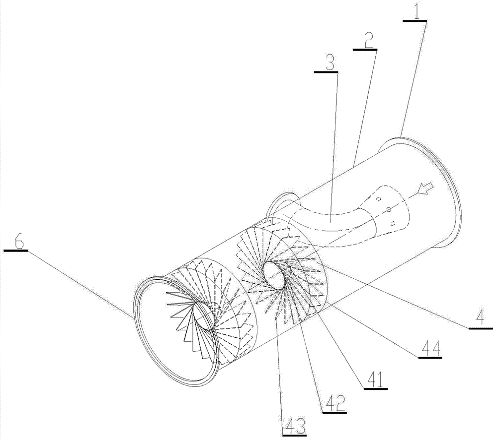
[0032] Such as figure 1 As shown, the embodiment of the swirl mixing device of the present invention consists of an inlet flange 1, a mixer body 2, a mixing medium mixing pipe 3, a swirler 4, and an outlet flange 6, and the components are sequentially connected by welding.

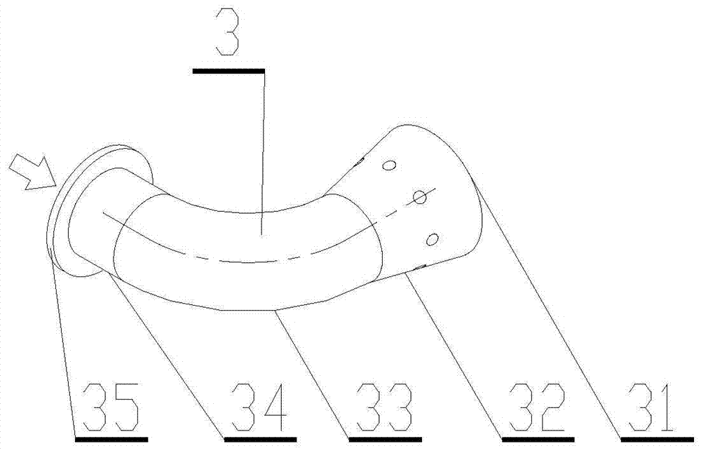
[0033] Such as figure 2 As shown, the mixing medium mixing pipe 3 is composed of a mixing cone block plate 31, a mixing pipe mixing cone 32, a 90° elbow 33 of the mixing pipe, a straight pipe section 34 of the mixing pipe, and a mixing pipe interface flange 35. In turn a solder connection is used. The mixing medium mixing pipe 3 and the mixer body 2 are connected by welding.

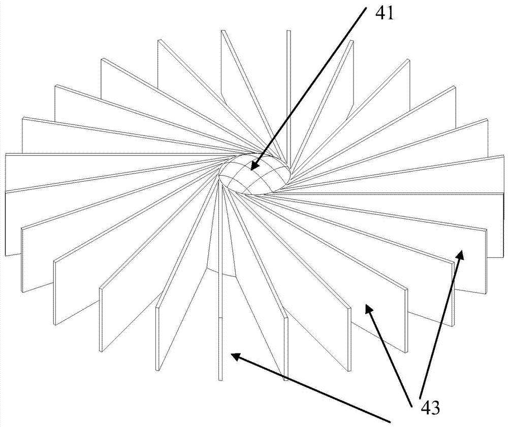
[0034] The swirler 4 is composed of a swirler head 41 , a swirler cone 42 , a swirler blade 43 and a swirler outer cylinder 44 . The parts are joined by welding in turn. The cyclone 4 and the mixer body 2 are connected by welding or flanges.

[0035] In use, the inlet flange 1 and the outlet flange 6 are respectively connected ...


PUM


Abstract

The invention discloses a swirling flow mixing device, which is invented to solve the stratification phenomenon that occurs during the mixing process of two or more gas media with different densities, thereby affecting the subsequent process production. The swirl mixing device of the present invention includes an inlet flange, a mixer cylinder, a mixing medium mixing pipe, a cyclone, an outlet flange, and the like. The cyclone comprises a cyclone head, a cyclone cone, and a cyclone vane. The swirling flow mixing device of the present invention has the characteristics of no external energy consumption, small resistance loss, uniform mixing, maintenance-free, and the length of the mixing section is 1 / 100-1 / 200 of natural mixing, which can greatly improve the uniformity of the mixing medium.

Description

technical field [0001] The invention relates to a swirl flow mixing device, in particular to mixing one or two or more gases of different densities into another gas of another density and forming a new mixed gas by means of a swirl plate to strengthen physical mixing. Background technique [0002] Industrial enterprise gas includes blast furnace gas, converter gas, coke oven gas, producer gas, smelting reduction gas, natural gas, chemical tail gas, liquefied petroleum gas, etc. The calorific value of these gases is different. ) specific calorific value requirements, one or several kinds of gas are required to be mixed. In the past, the general method is that one or more than one kind of gas is simply mixed into another gas and then mixed naturally through pipeline transportation. This natural The mixing method requires a long length of pipeline after the mixing point, which is generally about 100m to 200m according to the diameter of the pipe. However, due to the limitation ...

Claims


Application Information

Patent Timeline
Patent Type & Authority Patents(China)
IPC IPC(8): B01F5/06B01F3/02B01F23/10
Inventor 徐庆余杨猛
Owner HUATIAN ENG & TECH CORP MCC
Why Eureka
Try Eureka