Mould for U-shaped bolts

A technology for forming molds and bolts, which is applied in the field of U-shaped bolt forming molds, can solve the problems of increased manufacturing costs and inability to adjust, and achieve the effect of reducing manufacturing costs

Inactive Publication Date: 2015-11-11
上海东普起重机械有限公司
View PDF6 Cites 0 Cited by
  • Summary
  • Abstract
  • Description
  • Claims
  • Application Information

AI Technical Summary

Problems solved by technology

Since the U-shaped bolts are all made of steel, the workpiece will rebound slightly after being stamped and taken out. Therefore, the U-shaped cavity of the lower mold base must have a springback allowance in advance. However, in the existing U-shaped bolt forming mold , the springback allowance of the U-shaped cavity of the lower mold base is fixed and cannot be adjusted. Therefore, the existing U-shaped bolt forming molds can usually only be used for the processing and manufacturing of single-standard U-shaped bolts, which will cause enterprises to manufacture cost increase

Method used


Image

  • Mould for U-shaped bolts
  • Mould for U-shaped bolts

Examples


Embodiment Construction

[0010] The embodiments of the present invention are described in further detail below in conjunction with the accompanying drawings, but the present embodiments are not intended to limit the present invention. All similar structures and similar changes of the present invention should be included in the scope of protection of the present invention. The commas in all indicate the relationship between and.

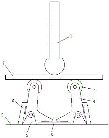
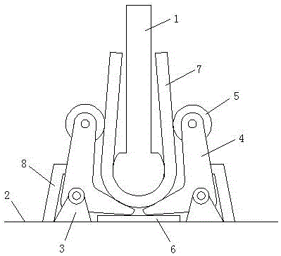
[0011] Such as Figure 1-Figure 2 As shown, a U-shaped bolt forming die provided by the embodiment of the present invention includes an upper die rod 1 and a lower die assembly, the bottom end surface of the upper die rod 1 is a convex arc surface, and it is characterized in that: the The lower mold assembly includes a base 2, and a lower mold support 3 on the left and right sides fixed on the base 2;

[0012] Each of the two lower mold supports 3 is pivotally provided with a swing arm 4 that can pivot up and down, and the pivots of the two swing arms 4 are parallel to each ...


PUM


Abstract

The invention discloses a mould for U-shaped bolts, and relates to the technical field of machine manufacturing. The technical aim that the manufacturing cost is reduced is achieved. The mould comprises an upper mould rod and a lower mould assembly. The end face of the bottom end of the upper mould rod is a convex arc face, and the lower mould assembly comprises a base and lower mould supports; the left side and the right side of the base are fixedly provided with one lower mould support, and the two lower mould supports are each provided with a swing arm in a pivotal manner, wherein the swing arms can rotate in a pivotal manner vertically; pivotal shafts of the two swing arms are parallel to each other, and the lower ends of the two swing arms are bent oppositely and are free of mutual interference; the top ends of the two swing arms are each provided with a roller, and rolling shafts of the rollers are parallel to the pivotal shafts of the swing arms; and a detachable springback base plate is fixed to the base, is located under the bending portions at the lower ends of the swing arms, and interferes with pivoting of the bending portions of the lower ends of the two swing arms. The mould can be used for machining and manufacturing the U-shaped bolts in various specifications.

Description

technical field [0001] The invention relates to mechanical manufacturing technology, in particular to the technology of a U-shaped bolt forming die. Background technique [0002] U-shaped bolts are all stamped and formed by molds during mass production. The existing U-shaped bolt forming dies are mainly composed of an upper mold rod and a lower mold base. When stamping, the workpiece is placed on the lower mold base, and the workpiece is pressed by the upper mold rod. The workpiece can be stamped into the U-shaped cavity of the lower mold base. Since the U-shaped bolts are all made of steel, the workpiece will rebound slightly after being stamped and taken out. Therefore, the U-shaped cavity of the lower mold base must have a springback allowance in advance. However, in the existing U-shaped bolt forming mold , the springback allowance of the U-shaped cavity of the lower mold base is fixed and cannot be adjusted. Therefore, the existing U-shaped bolt forming molds can usual...

Claims


Application Information

Patent Timeline
IPC IPC(8): B21D37/10
Inventor 李国建李站春
Owner 上海东普起重机械有限公司
Why Eureka
Try Eureka