
An automatic riveting machine

A riveting machine and automatic technology, which is applied in the direction of fasteners, buttons, buttons, etc., can solve the problems of large close-contact operation methods, poor riveting effect, and potential safety hazards, so as to achieve good riveting effect, The effect of eliminating hidden dangers and improving efficiency

Active Publication Date: 2017-02-01
SHISHI LONGXIANG HARDWARE PLASTIC PROD CO LTD
View PDF7 Cites 0 Cited by
  • Summary
  • Abstract
  • Description
  • Claims
  • Application Information

AI Technical Summary

Problems solved by technology

[0002] In the production and manufacturing process of metal buttons, it is often necessary to carry out further riveting work on some individual parts or assembled parts. In production, the parts are small in size and large in quantity, and each part must be riveted. , It takes a long time for a large amount. The riveting machine currently in use is still a traditional manual machine, including a workbench, a workframe set on the workbench, a punching head that can slide up and down on the workbench, and a connecting punch. The cutter head is used to manually control the control mechanism that the stamping cutter head slides up and down. When working, the staff will first place the parts to be riveted directly under the stamping cutter head, and then operate the manual control mechanism to lower the stamping cutter head. Press hard on the parts to complete the riveting of a part, and then manually operate the control mechanism to raise the stamping head, take out the riveted parts, and start the next riveting work. This traditional method is efficient. Very low, the effect of riveting is not good, and the operation method of close contact between the staff's hand and the machine during riveting has great potential safety hazards

Method used


Image

  • An automatic riveting machine
  • An automatic riveting machine
  • An automatic riveting machine

Examples


Embodiment Construction

[0043] In order to further explain the technical solution of the present invention, the present invention will be described in detail below through specific examples.

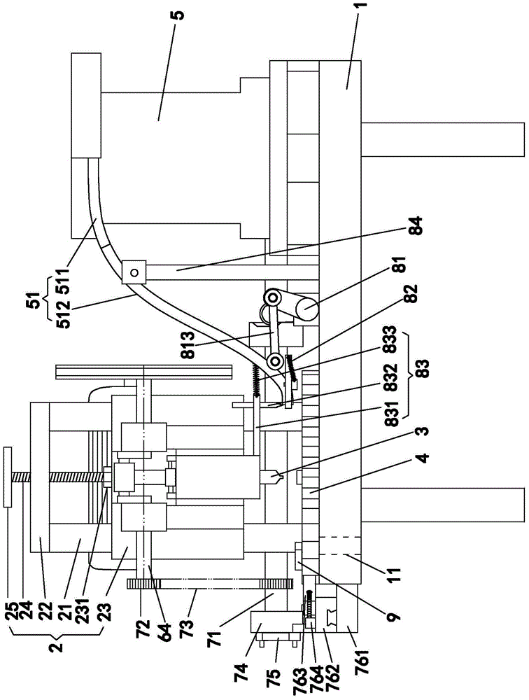
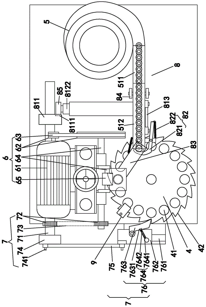
[0044] An automatic riveting machine, such as figure 1 and figure 2 Shown includes a workbench 1, a workframe 2 arranged on the workbench 1, and a stamping cutter head 3 which is arranged on the workbench 2 and can slide up and down relatively. The difference between the present invention and the prior art is that it also includes a The rotating working disk 4 set on the working table 1, the automatic discharge barrel 5 that automatically unloads the material onto the working disk 4, the driving mechanism 6 that drives the stamping cutter head 3 to slide up and down relative to the working frame 2, and the connecting driving mechanism 6 for transmission work The transmission mechanism 7 that the disk 4 rotates.

[0045] The automatic discharge barrel 5 is a well-known technical structure principle, and it is...


PUM


Abstract

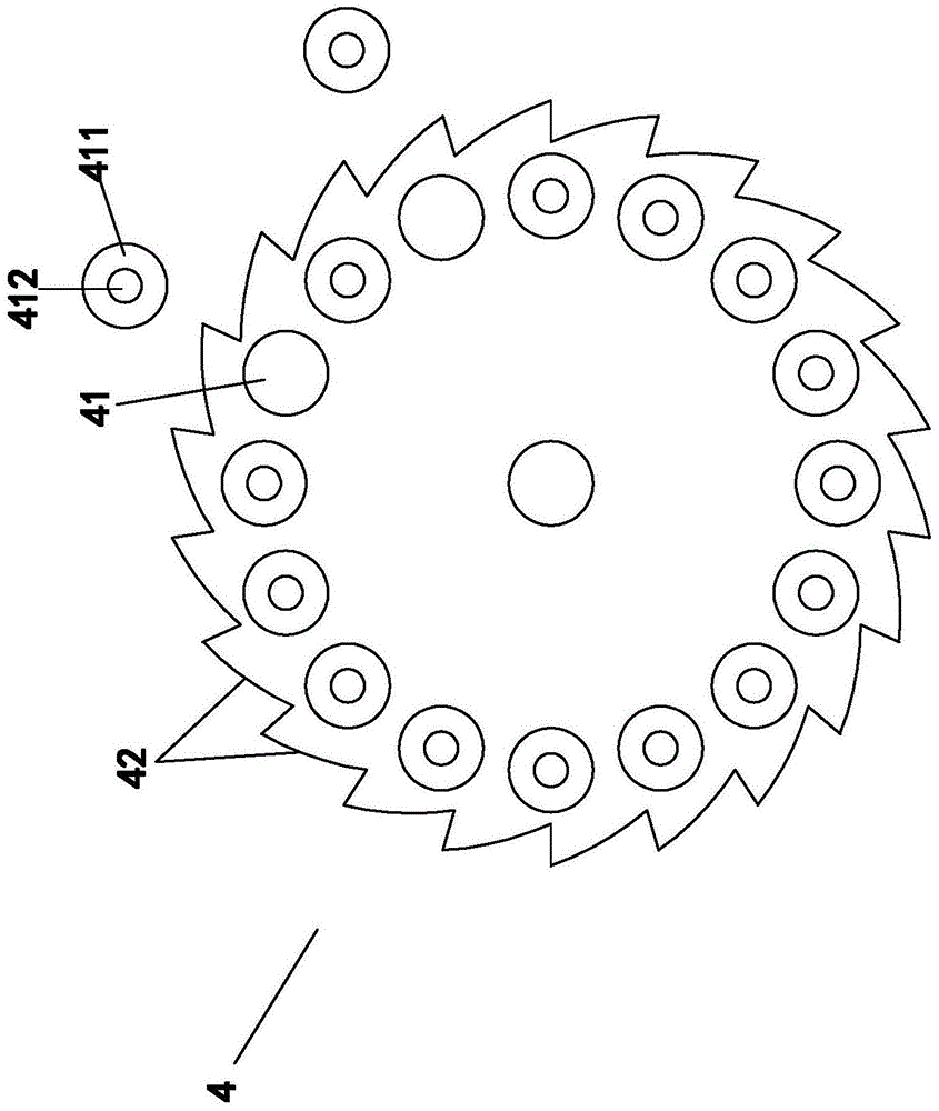
The invention discloses an automatic riveting machine, and relates to the field of riveting machinery of metal buttons. The automatic riveting machine comprises a workbench, an operating frame, a punching cutting head capable of sliding up and down, a rotatable operating disc, an automatic discharging barrel, a driving mechanism which drives the punching cutting head to slide and a transmission mechanism which drives the operating disc to rotate. The periphery, surrounding the rotation axis center, of the operating disc is evenly provided with workpiece holes penetrating the operating disc. The workpiece holes can be rotated to the position which corresponds to the punching cutting head and is under the punching cutting head. The workbench is provided with a discharging hole which can be communicated with the workpiece holes. The automatic discharging barrel is provided with a blanking groove extending to the operating disc. The workpiece holes can be rotated to the position which corresponds to discharging end openings of the blanking groove and is below the discharging end openings of the blanking groove. According to the structure of the riveting machine, automatic riveting operating can be achieved, the operating disc can be rotated synchronously and is provided with the multiple workpiece holes, automatic and accurate blanking can be achieved, automatic discharging can also be achieved, and the manual operation is not needed totally, so that the efficiency is greatly improved, the potential safety hazard is eliminated, the better and consistent riveting effect can be achieved, and the automatic riveting machine is suitable for riveting of various kinds of workpieces.

Description

technical field [0001] The invention relates to the field of riveting machinery for metal buttons. Background technique [0002] In the production and manufacturing process of metal buttons, it is often necessary to carry out further riveting work on some individual parts or assembled parts. In production, the parts are small in size and large in quantity, and each part must be riveted. , It takes a long time for a large amount. The riveting machine currently in use is still a traditional manual machine, including a workbench, a workframe set on the workbench, a punching head that can slide up and down on the workbench, and a connecting punch. The cutter head is used to manually control the control mechanism that the stamping cutter head slides up and down. When working, the staff will first place the parts to be riveted directly under the stamping cutter head, and then operate the manual control mechanism to lower the stamping cutter head. Press hard on the parts to comple...

Claims


Application Information

Patent Timeline
Patent Type & Authority Patents(China)
IPC IPC(8): B21D53/48B21D39/00
Inventor 吴朝旭孙德来庄君钰
Owner SHISHI LONGXIANG HARDWARE PLASTIC PROD CO LTD
Learn More