Self-adaptation part plugging device

A plug-in device and self-adaptive technology, applied in metal processing, metal processing equipment, manufacturing tools, etc., to achieve the effect of improving the applicability of equipment

Inactive Publication Date: 2015-11-11
FORYOU GENERAL ELECTRONICS
View PDF5 Cites 6 Cited by
  • Summary
  • Abstract
  • Description
  • Claims
  • Application Information

AI Technical Summary

Problems solved by technology

Therefore, the current plug-in material assembly technology needs to be improved

Method used


Image

  • Self-adaptation part plugging device
  • Self-adaptation part plugging device
  • Self-adaptation part plugging device

Examples


Embodiment Construction

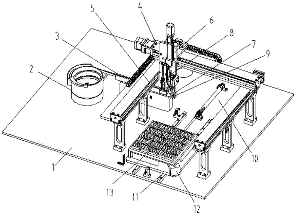
[0026] The present invention will be described in detail below in conjunction with the accompanying drawings and specific embodiments, where the schematic embodiments and descriptions of the present invention are used to explain the present invention, but not to limit the present invention.

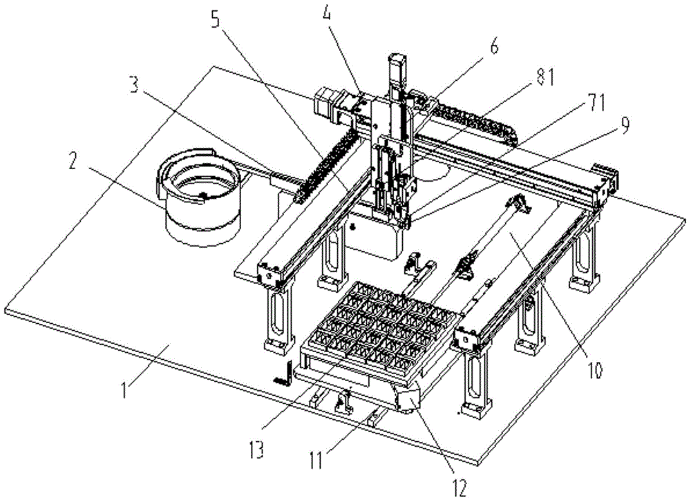
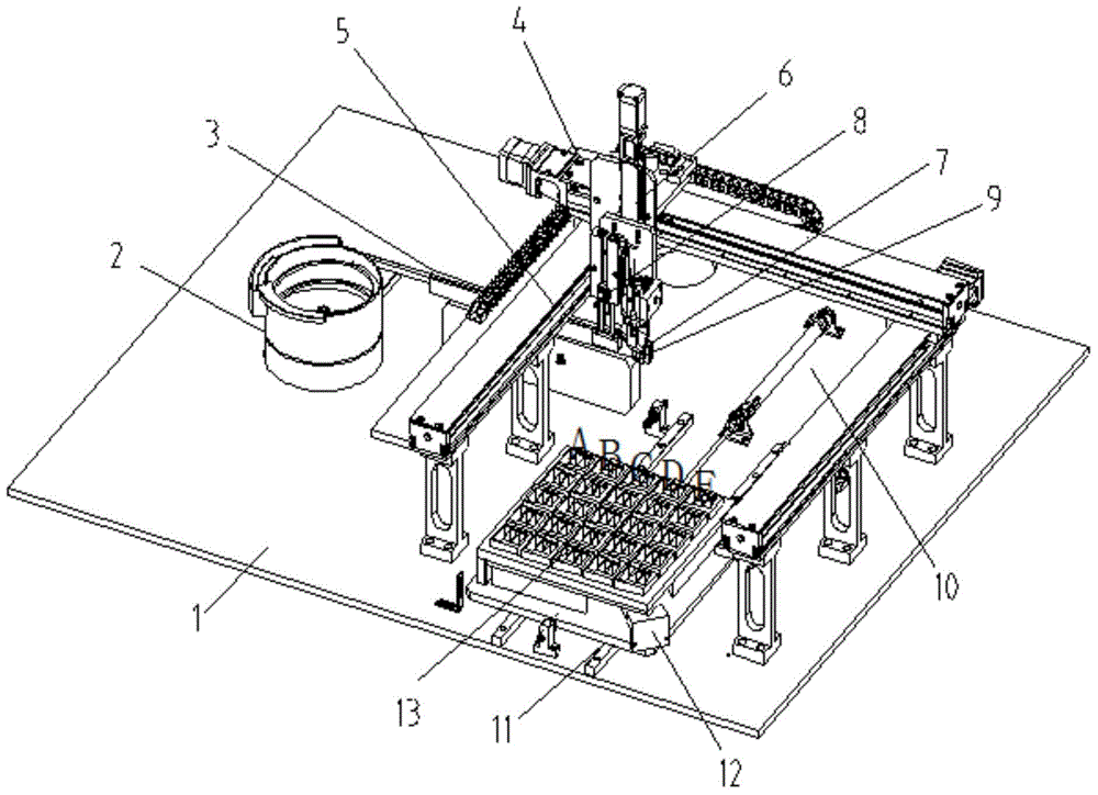
[0027] Such as figure 1 As shown, this embodiment provides an adaptive plug-in device for objects to be inserted, including a mounting base 1, on which a feeding unit, a socket displacement unit, a displacement unit for objects to be inserted, and a displacement unit for objects to be inserted are arranged. The holding device 7 for the object to be inserted and the pressing device 8 for the object to be inserted on the bit unit;

[0028] In this embodiment, the feeding unit includes a vibration plate 2 and a direct vibration device 3 connected to the vibration plate 2 .

[0029] The displacement unit of the object to be inserted is driven by a motor controlled by the controller, and the ...


PUM


Abstract

The invention relates to a self-adaptation part plugging device which comprises an installation base plate. A feeding unit, a socket moving unit, a to-be-plugged part moving unit, a to-be-plugged part clamping device and a to-be-plugged part press-in device are arranged on the installation base plate, wherein the to-be-plugged part clamping device and the to-be-plugged part press-in device are arranged on the to-be-plugged part moving unit. The to-be-plugged part moving unit is driven by a motor controlled by a controller, is a three-dimensional moving unit and comprises an X-axis moving device, a Y-axis moving device and a Z-axis moving device which are mutually matched. The to-be-plugged part clamping device and the to-be-plugged part press-in device are arranged on the Z-axis moving device. The self-adaptation part plugging device has the following technical effects that automatic part plugging work is achieved, and the applicability of the self-adaptation part plugging device is improved; and due to the fact that the automatic part plugging operation replaces the manual operating mode, the installation intensity is reduced, and the operating efficiency is improved.

Description

technical field [0001] The invention relates to the technical field of plug-in material assembly, in particular to an adaptive plug-in device. Background technique [0002] In the production process, there are usually many plug-in materials that need to be assembled, which is usually done by hand at present. For example, in the production process of automotive electronic products, a fuse needs to be inserted into the power socket to provide overcurrent protection. However, the current installation method of the fuse is manual plug-in installation, and the fuse needs to be pressed by a manual press-in machine. The strong contact with the power socket leads to high installation intensity of manual work, and the operators are prone to fatigue; the operations of inserting the safety tube and pressing into the base of the power socket are carried out separately and in batches, with many repetitive actions, many actions without added value, and low operating efficiency. Moreover,...

Claims


Application Information

Patent Timeline
Patent Type & Authority Applications(China)
IPC IPC(8): B23P19/027
CPCB23P19/027B23P19/001B23P19/007
Inventor 施周志张京梁
Owner FORYOU GENERAL ELECTRONICS
Why Eureka
Try Eureka