Paver advancing, steering and supporting device

A support device and paver technology, which is applied to fluid steering mechanisms, roads, road repairs, etc., can solve the problems of unobstructed 360° rotation, uneven force on steering support devices, etc.

Active Publication Date: 2015-11-11
SHANDONG VANSE MECHANICAL TECH CO LTD
View PDF7 Cites 0 Cited by
  • Summary
  • Abstract
  • Description
  • Claims
  • Application Information

AI Technical Summary

Problems solved by technology

[0004] The purpose of the present invention is to provide a paver traveling steering support device, which aims to solve the problem that the existing steering support device is unevenly stressed and unable to realize unobstructed 360° rotation

Method used


Image

  • Paver advancing, steering and supporting device
  • Paver advancing, steering and supporting device
  • Paver advancing, steering and supporting device

Examples


Embodiment 1

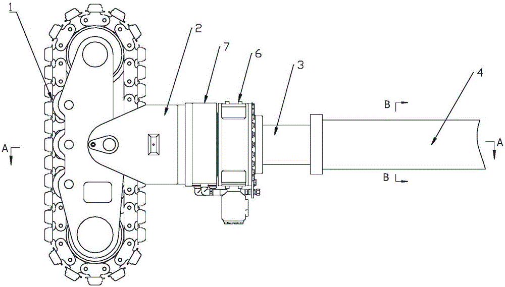
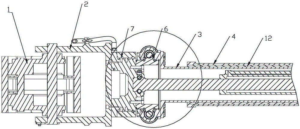
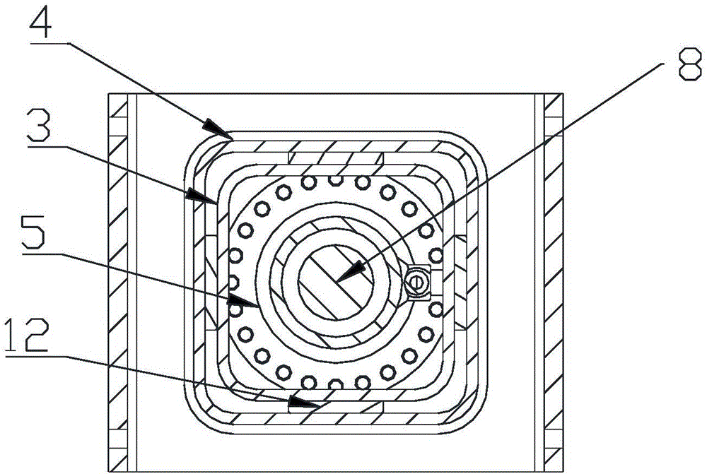
[0024] like Figure 1-Figure 6 As shown in , a paver travel steering support device, which includes a travel device 1, a fixed bracket 2, a lifting column 3, a support body 4, a thrust cylinder 5, a rotary drive device 6 and an oil circuit rotary joint 7, wherein the travel device 1. The traveling device can specifically be a tire or a crawler belt. A fixed bracket 2 is fixed above the traveling device 1. An oil circuit rotary joint 7 is fixed above the fixed bracket 2. A rotary drive device 6 is fixed on the upper end of the oil circuit rotary joint 7. The upper end of the slewing drive device 6 is vertically fixed with a lifting column 3. The lifting column 3 and the support body 4 are hollow square prisms with the same shape inside and outside. The lifting column 3 is covered with a support body 4. A slide bar 12 is provided between the opposite surfaces of the outer walls of the column 3, the top of the inner cavity of the support body 4 is fixedly connected with the top o...

Embodiment 2

[0028] like Figure 7-Figure 9 A paver driving steering support device shown in , the overall structure of this embodiment 2 is the same as that of embodiment 1, the difference is that the lifting column 3 and the support body 4 are hollow cylinders with the same shape, and the lifting column jacket There is a support body 4, and a lifting column positioning device 29 is also provided on the lifting column. The relative chute 13 is fixedly fitted with a positioning ring 14 on the outer wall at the bottom of the lifting column 3, and slides the set lifting positioning disc 15 on the outer wall of the lifting column 3 above the positioning ring 14, and is fixedly installed on the inner wall of the lifting positioning disc 15. There are two sliders 16, the sliders 16 slide up and down and are clamped on the chute 13, a support body 4 is fixed above the lifting positioning plate 15, and a reciprocating motion bearing 17 is arranged between the support body 4 and the lifting column, ...


PUM


Abstract

The invention discloses a paver advancing, steering and supporting device. The paver advancing, steering and supporting device comprises an advancing device, a fixed support, a lifting column, a supporting body, a thrust oil cylinder, a rotation drive device and an oil way rotation connector. The fixed support is fixedly arranged on the upper portion of the advancing device. The oil way rotation connector is fixedly arranged on the upper portion of the fixed support. The rotation drive device is fixedly arranged at the upper end of the oil way rotation connector. The lifting column is vertically and fixedly arranged at the upper end of the rotation drive device. The lifting column and the supporting body are hollow cylinders which are arranged in an inside-outside sleeved mode and are of the same shape. The lifting column is arranged in an inner cavity of the supporting body. The top of the inner cavity of the supporting body is fixedly connected with the top of a cylinder body of the thrust oil cylinder. The thrust oil cylinder is arranged in an inner cavity of the lifting column. The top of a piston rod of the thrust oil cylinder penetrates through the inner cavity of the lifting column and the rotation drive device to be fixed into a piston rod fixing base on the top of the oil way rotation connector. A connection groove is formed in the top of the piston rod. An annular piston rod fixing groove corresponding to the connection groove is formed in the piston rod fixing base. Piston rod positioning steel balls are arranged in the piston rod fixing groove.

Description

Technical field: [0001] The invention relates to the field of paver equipment, in particular to a paver traveling steering support device. Background technique: [0002] The existing slip-form paver crawler steering mechanism is realized by an oil cylinder push-pull device. In this way, the steering angle is limited and cannot run laterally. The crawler lifting and rotating positioning mechanism adopts flat key positioning and outer folding reinforcing plate. The contact surface between the key and the keyway is not strong enough, and the outer folding reinforcing plate makes up for the strength. If the key is thicker, the keyway must be opened deeper, so the lifting column material must be thicker. The weight of the whole machine is increased. [0003] The disadvantages of the existing paver travel support steering device mainly include: first, the existing steering device cannot realize 360 ​​° rotation without obstacles, because the hydraulic motor is installed on the cr...

Claims


Application Information

Patent Timeline
Patent Type & Authority Applications(China)
IPC IPC(8): B62D5/06E01C19/12
Inventor 陈建军
Owner SHANDONG VANSE MECHANICAL TECH CO LTD
Why Eureka
Try Eureka