Movable building lifting device

A mobile and architectural technology, applied in the direction of hoisting device, hoisting equipment braking device, hoisting device, etc., can solve the problems of inconvenient construction personnel to move the hoisting device, increase the workload of construction personnel, and reduce construction costs. , to achieve the effect of fast and convenient movement, convenient construction work, and improve work efficiency

Active Publication Date: 2018-12-07
章志尚
View PDF5 Cites 2 Cited by
  • Summary
  • Abstract
  • Description
  • Claims
  • Application Information

AI Technical Summary

Problems solved by technology

[0005] Aiming at the deficiencies of the prior art, the present invention provides a movable building lifting device, which solves the problem that the existing design method is very inconvenient for the construction personnel to move the lifting device, and the construction personnel need to spend a lot of time to lift the lifting device every time. The device is disassembled and reassembled and fixed at another construction location, which greatly increases the work load of the construction personnel, reduces the work efficiency of the construction personnel, cannot realize the fast and convenient movement of the lifting device as a whole, and cannot reduce the construction cost question of purpose

Method used


Image

  • Movable building lifting device
  • Movable building lifting device
  • Movable building lifting device

Examples


Embodiment Construction

[0026] The following will clearly and completely describe the technical solutions in the embodiments of the present invention with reference to the accompanying drawings in the embodiments of the present invention. Obviously, the described embodiments are only some, not all, embodiments of the present invention. Based on the embodiments of the present invention, all other embodiments obtained by persons of ordinary skill in the art without making creative efforts belong to the protection scope of the present invention.

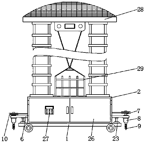
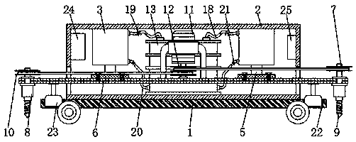
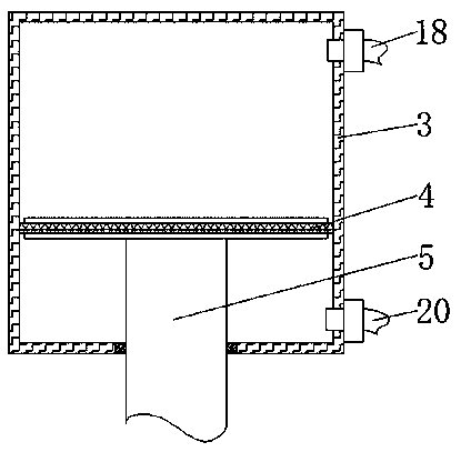
[0027] see Figure 1-5, the embodiment of the present invention provides a technical solution: a movable building lifting device, including a bottom plate 1, the top of the bottom plate 1 is fixedly connected to an organic case 2, and the two sides of the inner wall of the case 2 are respectively fixedly connected to a battery 24 and a controller 25, The storage battery 24 can be used to energize the entire lifting device. The model of the controller 25 is ARM...


PUM


Abstract

The invention discloses a movable building lifting device and relates to the technical field of building equipment. The movable building lifting device comprises a bottom plate. The top of the bottomplate is fixedly connected with a machine case. Two sides of the top of the inner wall of the machine case are fixedly connected with hydraulic telescopic cylinders. A piston disc is slidably connected inside each hydraulic telescopic cylinder. A hydraulic rod is fixedly connected at the bottom of each piston disc. The bottom end of each hydraulic rod penetrates through the corresponding hydraulictelescopic cylinder and extends to the bottom of the corresponding hydraulic telescopic cylinder. The movable building lifting device well solves the problem that a lifting device is inconvenient forconstruction personnel to move, it is not necessary for the construction personnel to spend a lot of time to disassemble and reassemble the lifting device and fix the lifting device at another construction position, the work burden of the construction personnel is reduced, the work efficiency of the construction personnel is improved, the quick and convenient movement of the lifting device as a whole is realized, the purpose of reducing the construction cost is achieved, and thus the construction work of the construction personnel is greatly facilitated.

Description

technical field [0001] The invention relates to the technical field of construction equipment, in particular to a movable construction lifting device. Background technique [0002] Building construction refers to the production activities in the implementation stage of engineering construction. It is the construction process of various buildings. It can also be said to be the process of turning various lines on the design drawings into physical objects at designated locations. It includes basic engineering construction. , main structure construction, roofing engineering construction and decoration engineering construction, etc., the construction site is called "building construction site" or "construction site", also called a construction site. The design blueprint refers to the production activities for the construction of various building products in a certain space and time. It includes the entire production process from construction preparation, groundbreaking to project...

Claims


Application Information

Patent Timeline
Patent Type & Authority Applications(China)
IPC IPC(8): B66F11/04
CPCB66C1/16B66C5/02B66C9/08B66C9/10B66C9/14F16F15/022F16F15/023F16F15/046F16F15/06F16F2222/12F16F2238/026
Inventor 章志尚
Owner 章志尚
Why Eureka
Try Eureka