
Die machining equipment

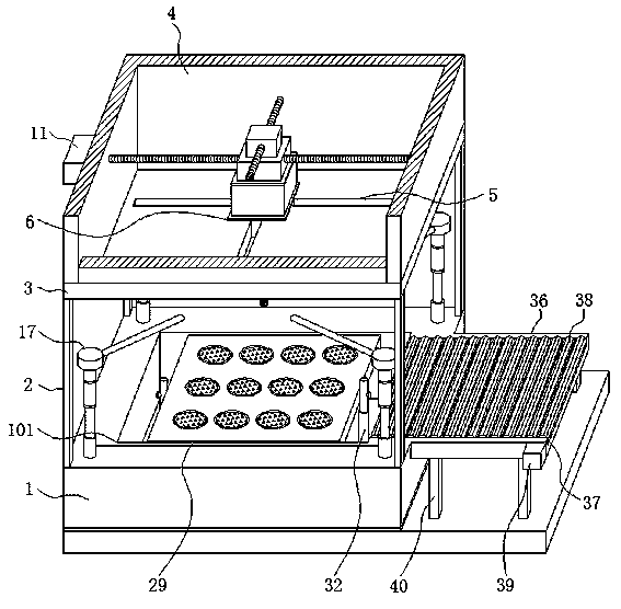
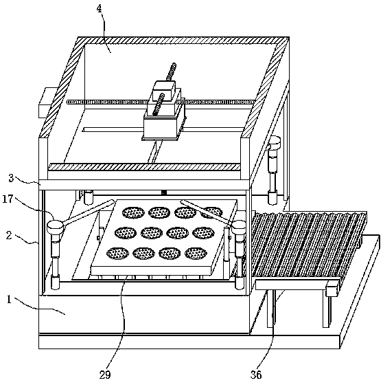
A mold processing and equipment technology, applied in the field of mold processing equipment, can solve problems such as difficult angle inclination, complicated clamping steps, complex fixture structure design, etc., and achieve the effect of fast positioning and convenient fixing

Inactive Publication Date: 2020-06-19
DONGGUAN XIANGFEI INTELLIGENT EQUIP TECH CO LTD
View PDF0 Cites 2 Cited by
  • Summary
  • Abstract
  • Description
  • Claims
  • Application Information

AI Technical Summary

Problems solved by technology

[0004] However, in the existing mold processing equipment, the design of the fixture structure is complex, so that the mold needs to go through complicated clamping steps, and after the mold is clamped, it is not easy to tilt the angle. When the inclined surface needs to be processed, the mold needs to be clamped obliquely. This clamping method is not easy to control, and the angle of the final mold slope cannot be accurately guaranteed

Method used


Image

  • Die machining equipment
  • Die machining equipment
  • Die machining equipment

Examples


Embodiment Construction

[0028] The following will clearly and completely describe the technical solutions in the embodiments of the present invention with reference to the accompanying drawings in the embodiments of the present invention. Obviously, the described embodiments are only some, not all, embodiments of the present invention.

[0029] In the description of the present invention, unless otherwise stated, the meaning of "plurality" is two or more; the terms "upper", "lower", "left", "right", "inner", "outer" , "front end", "rear end", "head", "tail", etc. indicate the orientation or positional relationship based on the orientation or positional relationship shown in the drawings, and are only for the convenience of describing the present invention and simplifying the description, rather than Indicates or implies that the device or element referred to must have a particular orientation, be constructed and operate in a particular orientation, and therefore should not be construed as limiting the...


PUM


Abstract

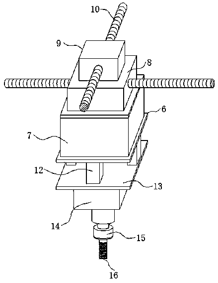
The invention discloses die machining equipment, and relates to the technical field of die machining. The die machining equipment specifically comprises a base, a milling head, cleaning mechanisms, afixture and a conveying device; supporting rods are vertically welded to four corners of the upper surface of the base; a protective box is welded to the upper portion of a top plate, and the millinghead is installed in the protective box; the cleaning mechanisms are vertically installed at four portions of the upper part of the base; the middle of the base is provided with a placement groove, and the fixture is placed in the placement groove; one side of the base is provided with the conveying device; the die machining equipment is provided with the fixture, the fixture adopts the negative pressure suction principle to fix a to-be-machined die, and the advantages of being high in positioning speed, convenient to fix, firm and stable are achieved; through extracting and contracting of a hydraulic lifting rod, the height of a clamping plate can be adjusted; and electric push rods are used for controlling the whole clamping plate to be inclined, and accordingly, the die fixed to the clamping plate is driven to rotate by a certain angle so that die machining can be completely better, faster and more efficiently.

Description

technical field [0001] The invention relates to the technical field of mold processing, in particular to a mold processing equipment. Background technique [0002] A mold is a tool used to make shaped objects. This tool is composed of various parts. Different molds are composed of different parts. The mold mainly realizes the processing of the shape of the object through the change of the physical state of the formed material. The title of "mother", the precision and quality of the mold are directly related to the precision and quality of the molded product, so in the production and processing of the mold, it is necessary to pay special attention to the dimensional accuracy of the mold cavity. [0003] Most of the existing molds are processed by milling, and the selected processing equipment is mostly CNC milling machines or machining centers. CNC machine tools are used to manufacture molds, which have strong stability, high precision, and faster processing speed than ordina...

Claims


Application Information

Patent Timeline
IPC IPC(8): B23C3/00B23Q3/04B23Q3/08B23Q5/40B23Q7/05B23Q11/00
CPCB23C3/00B23Q3/04B23Q3/088B23Q5/40B23Q7/055B23Q11/005
Inventor 邓珊陈创佳
Owner DONGGUAN XIANGFEI INTELLIGENT EQUIP TECH CO LTD
Learn More