A paver traveling support device

A support device and paver technology, applied in the direction of steering mechanism, transportation and packaging, roads, etc., can solve the problems of inability to realize rotation, complicated processing technology, high manufacturing cost, etc., achieve good stability, reduce manufacturing cost, and simplify processing The effect of the manufacturing process

Active Publication Date: 2017-12-29
SHANDONG VANSE MECHANICAL TECH CO LTD
View PDF7 Cites 0 Cited by
  • Summary
  • Abstract
  • Description
  • Claims
  • Application Information

AI Technical Summary

Problems solved by technology

[0004] The first object of the present invention is to provide a traveling support device for a paver to solve the problems of the existing traveling support device with cumbersome structure, complicated processing technology and high manufacturing cost
[0005] The second object of the present invention is to provide a steering support device for paver travel, which aims to solve the problem that the existing steering support device is unevenly stressed and unable to realize unobstructed 360° rotation

Method used


Image

  • A paver traveling support device
  • A paver traveling support device
  • A paver traveling support device

Examples


Embodiment 1

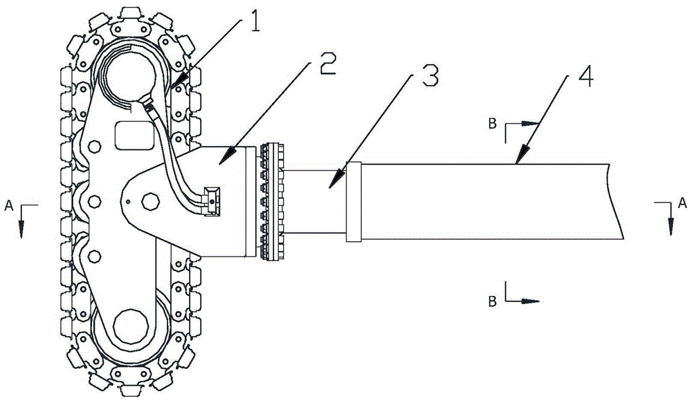
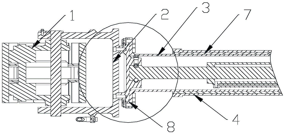
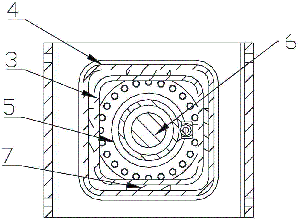
[0026] Embodiment 1: as Figure 1-Figure 4 As shown in , a paver travel support device, which includes a travel device 1, a fixed bracket 2, a lifting column 3, a support body 4, and a thrust cylinder 5, wherein the travel device can specifically be a tire or a crawler belt, and the travel device 1 A fixed support 2 is fixed above the fixed support 2, and a lifting column 3 is vertically fixed on the fixed support 2. The bottom end of the lifting column 3 is fixed on the fixed support 2. The lifting column 2 and the support body 4 are hollow regular prisms with the same shape. The column 3 is set in the inner cavity of the supporting body 4, the top of the inner cavity of the supporting body 4 is fixedly connected with the top of the cylinder body of the thrust cylinder 5, the thrust cylinder 5 is placed in the inner cavity of the lifting column 3, and the top end of the piston rod 6 of the thrust cylinder 5 is placed on the lifting At the bottom of the inner cavity of the col...

Embodiment 2

[0028] Embodiment 2: as Figure 5-Figure 9A paver travel steering support device shown in , which includes a travel device 1, a fixed bracket 2, a lifting column 3, a support body 4, a thrust cylinder 5, a rotary drive device 12 and an oil circuit rotary joint 13, in the travel device 1 A fixed bracket 2 is fixed above the fixed bracket 2, an oil circuit rotary joint 13 is fixed above the fixed bracket 2, a rotary drive device 12 is fixed on the upper end of the oil circuit rotary joint 13, and a lifting column 3 is vertically fixed on the upper end of the rotary drive device 12 , the lifting column 3 and the supporting body 4 are hollow regular prisms with the same shape, the lifting column 3 is arranged in the inner cavity of the supporting body 4, the top of the inner cavity of the supporting body 4 is fixedly connected with the cylinder top of the thrust cylinder 5, and the thrust cylinder 5 is placed The inner cavity of the lifting column 3, the piston rod 6 of the thrust...


PUM


Abstract

The invention discloses a traveling support device for a paver, which comprises a traveling device, a fixed bracket, a lifting column, a support body and a thrust oil cylinder, wherein a fixed bracket is fixed above the traveling device, and a vertical fixed device is fixed on the fixed bracket. There is a lifting column, the bottom end of the lifting column is fixed on the fixed bracket, the lifting column and the support body are hollow regular prisms with the same shape, the lifting column is arranged in the cavity of the support body, and the top of the support body cavity is fixedly connected with the top of the thrust cylinder. The thrust oil cylinder is placed in the inner cavity of the lifting column, the top end of the piston rod of the thrust oil cylinder is placed at the bottom of the inner cavity of the lifting column, and a slider is provided between the opposite surfaces of the inner wall of the support and the outer wall of the lifting column. The advantages are: the lifting column and the support body use polygonal column tubes to replace the cylindrical tubes in the existing traveling support device, the regular prism structure is simple and stable, the manufacturing process is simplified, and the manufacturing cost is reduced.

Description

Technical field: [0001] The invention relates to the field of paver equipment, in particular to a paver traveling support device. Background technique: [0002] The existing slip-form paver crawler steering mechanism is realized by an oil cylinder push-pull device. In this way, the steering angle is limited and cannot run laterally. The existing crawler lifting and rotating positioning mechanism adopts flat key positioning and outer folding reinforcement plate. The contact surface between the key and the keyway is not strong enough, and the strength is made up by the outer folding reinforcement plate. If the key is thicker, the keyway must be deep, so the lifting column material needs Thickening causes the weight of the whole machine to increase. [0003] In the patent application number ZL201301459839, the paver travel support device and the paver travel support lifting steering device are disclosed. The support body and the lifting column are cylindrical hollow bodies. Th...

Claims


Application Information

Patent Timeline
Patent Type & Authority Patents(China)
IPC IPC(8): B62D11/00E01C19/12
Inventor 刘建华陈建军
Owner SHANDONG VANSE MECHANICAL TECH CO LTD
Why Eureka
Try Eureka