Self-centering buckling-restrained brace beam-column joint

A technology of anti-buckling braces and beam-column joints, applied in the direction of earthquake resistance, building components, buildings, etc., can solve the problems of joints that are prone to brittle failure, unsuitable for continued use, and affect the function of the structure, so as to extend the service life, Rotation constraints reduce and eliminate the effect of residual deformation

Active Publication Date: 2015-11-11
HARBIN INST OF TECH AT WEIHAI
View PDF5 Cites 21 Cited by
  • Summary
  • Abstract
  • Description
  • Claims
  • Application Information

AI Technical Summary

Problems solved by technology

[0005] The present invention provides a self-resetting anti-buckling support beam-column joint to solve the problem that the existing self-resetting anti-buckling support diagonal arrangement scheme will affect the use function of the structure, and there are still beam-column joints in the existing frame steel structure Most of them use rigid connection or semi-rigid connection. The joints of this structure are prone to brittle failure. Even if the building does not collapse after an earthquake, it is dangerous and not suitable for continued use.

Method used


Image

  • Self-centering buckling-restrained brace beam-column joint
  • Self-centering buckling-restrained brace beam-column joint
  • Self-centering buckling-restrained brace beam-column joint

Examples


specific Embodiment approach 1

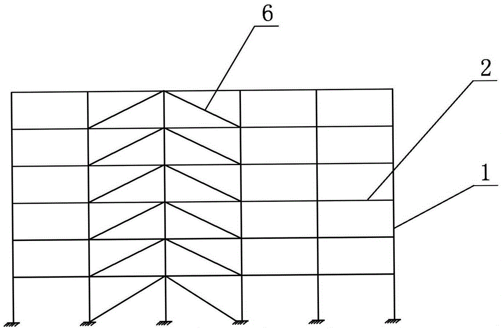
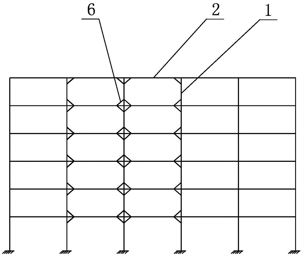
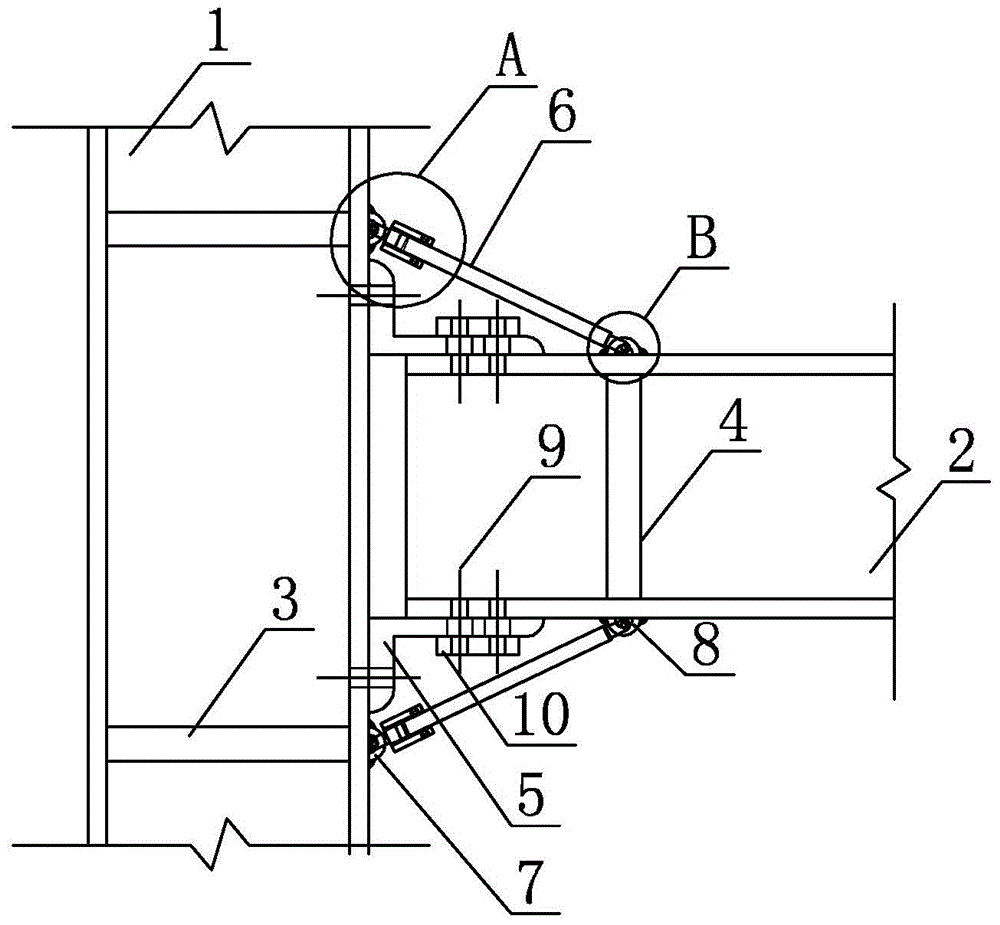
[0027] Specific implementation mode one: combine figure 1 , figure 2 , image 3 , Figure 4 , Figure 5 , Figure 6 and Figure 7 To illustrate this embodiment, this embodiment includes a column 1, a beam 2, two connecting plates 5, two self-resetting buckling-resistant support members 6, a plurality of bolts 9, a plurality of column stiffeners 3 and a plurality of beam stiffeners 4, A gap is set between the column 1 and the beam 2, a plurality of column stiffeners 3 are distributed on the column 1 along the length direction of the column 1, and a plurality of beam stiffeners 4 are distributed on the beam 2 along the length direction of the beam 2, two Connecting plates 5 are respectively arranged on the upper end and the lower end of the beam 2, each connecting plate 5 is L-shaped, the vertical plate section of each connecting plate 5 is connected with the column 1 flange by bolts 9, each connecting plate 5 The horizontal plate section and the vertical plate section ar...

specific Embodiment approach 2

[0029] Specific implementation mode two: combination image 3 This embodiment will be described. In this embodiment, the connecting plate 5 is a first angle steel. Other components and connections are the same as those in the first embodiment.

specific Embodiment approach 3

[0030] Specific implementation mode three: combination Figure 7 , Figure 8 , Figure 9 , Figure 10 , Figure 11 and Figure 12 Describe this embodiment, the self-resetting anti-buckling support member 6 in this embodiment includes a square outer sleeve 6-1, a square inner sleeve 6-2, a first end plate 6-5, a second end plate 6-6, a first Convex connecting plate 6-10, second convex connecting plate 6-11, two energy-dissipating inner core plates 6-3, multiple reset ribs 6-4, two connecting plates 6-7 and two pairs of second angle steels 6-8, the first convex connecting plate 6-10 is arranged between two energy-dissipating inner core plates 6-3, and the upper side wall and the lower side wall of the first convex connecting plate 6-10 Each is affixed to an energy-dissipating inner core board 6-3, and each connection plate 6-7 is arranged outside the corresponding energy-dissipating inner core board 6-3 and the two are affixed; the outside of the square outer sleeve 6-1 A ...


PUM


Abstract

The invention relates to a joint for building structures, relates to a self-centering buckling-restrained brace beam-column joint and aims to solve the problem that structural application functions of an existing self-centering buckling-restrained brace in a diagonal placement scheme may be influenced and the problem that existing steel-frame beam-column joints are mostly connected rigidly or semi-rigidly, the joint of such structure easily suffers brittle failure, and after an earthquake, dangers still exist and continual application is unavailable even after the building does not collapse. Gaps are provided among columns and beams, a plurality of column stiffening ribs are distributed on the columns, the beam stiffening ribs are distributed on the beams, two connecting plates are disposed on upper and lower flanges of one beam; each connecting plate is L shaped and is provided with a plurality of bolt holes; a vertical segment of each connecting plate is connected with a column plug through bolts; each bolt penetrate a corresponding bolt hole so as to connect the connecting plates and the girder; a self-centering buckling-restrained supporting member is correspondingly disposed on the outer side of each connecting board.

Description

technical field [0001] The invention specifically relates to a self-resetting anti-buckling support beam-column joint, which belongs to the field of construction. Background technique [0002] Most of the beam-column joints of traditional frame steel structures are rigidly or semi-rigidly connected to increase the rigidity of the structure. Among them, before the Northridge Earthquake, the rigid joints before the Northridge Earthquake were usually welded through the flanges of beams and columns. However, the survey after the Northridge Earthquake showed that the joints of this structure are prone to brittle failure, even if it did not collapse, it is not suitable for continued use after the earthquake. Due to the above reasons, semi-rigid joints have been more developed in the following period. Although the deformation capacity of the structure has been greatly improved, there are still residual deformation and damage to the main structure. An important reason for the abov...

Claims


Application Information

Patent Timeline
Patent Type & Authority Applications(China)
IPC IPC(8): E04B1/58E04B1/98
Inventor 刘璐李伟吴斌欧进萍
Owner HARBIN INST OF TECH AT WEIHAI
Why Eureka
Try Eureka