Leveling head

A technology of leveling head and flat plate, which is applied in the field of leveling head, can solve the problems that the flat plate cannot move vertically and the use effect is poor, and achieve the effect of improving work efficiency and reducing cost

Active Publication Date: 2015-11-11
SHANDONG VANSE MECHANICAL TECH CO LTD
View PDF5 Cites 8 Cited by
  • Summary
  • Abstract
  • Description
  • Claims
  • Application Information

AI Technical Summary

Problems solved by technology

[0003] The purpose of the present invention is to provide a leveling head, aiming to solve the problem that the trowel plate cannot move vertically and the use effect is poor in the prior art

Method used


Image

  • Leveling head
  • Leveling head
  • Leveling head

Examples


Embodiment 1

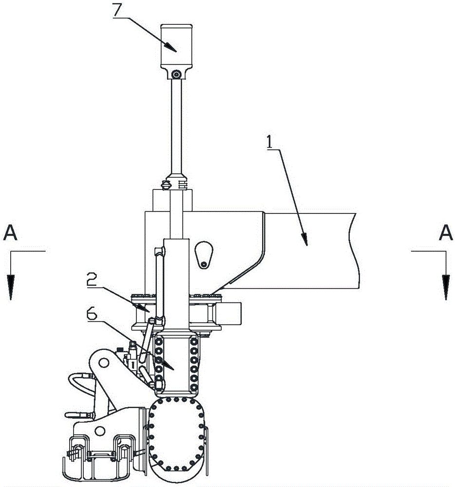
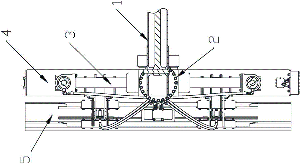
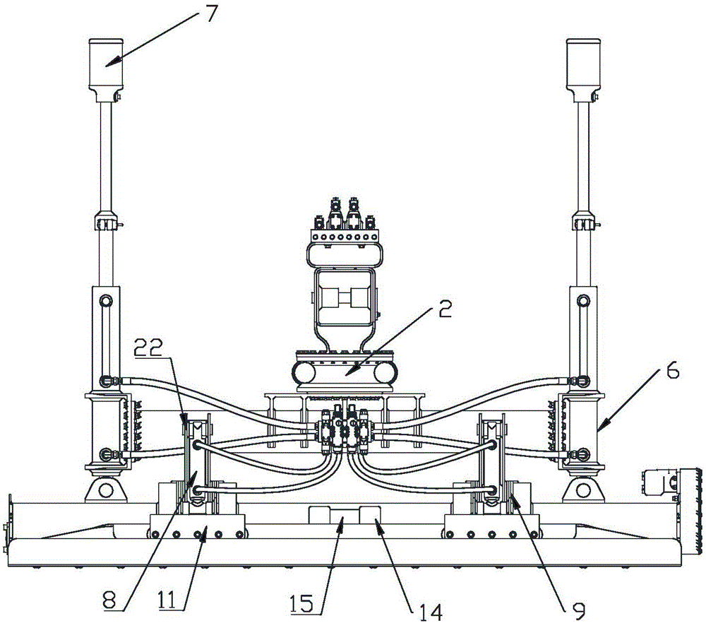
[0018] Embodiment 1: A leveling head, which includes a telescopic beam 1, a rotary joint 2, a leveling head beam 3, a spiral stirring distribution box 4, and a wiper plate 5 arranged sequentially from top to bottom, wherein, the front end of the telescopic beam 1 is provided below There is a rotary joint 2, and the telescopic beam 1 drives the rotary joint 2 to expand and contract. The lower end of the rotary joint 2 is horizontally fixedly connected to the leveling beam 3, and the middle part of the leveling beam 3 is fixedly connected to the lower end of the rotary joint 2; A double-rod cylinder 6 is fixed vertically; a sensor 7 is arranged on the top of the upper piston rod of the double-rod cylinder 6 to control the movement of the sensor 7 in the vertical direction, and the sensor 7 is used to collect operation information and transmit it to the control system , realize the automatic control of leveling process, sensor 7 can be laser sensor etc.; The horizontal angle adju...

Embodiment 2

[0021] Embodiment 2: The overall structure of this embodiment is consistent with that of Embodiment 1, the only difference being that the telescopic beam 1 includes a hollow socketed telescopic beam main body 16, a primary telescopic beam 17 and a secondary telescopic beam 18, and the telescopic beam main body 16 The front end is inserted into the primary telescopic beam 17, and the secondary telescopic beam 18 is inserted into the front end of the primary telescopic beam 17. A telescopic oil cylinder 19 is arranged in the telescopic beam main body 16, and the telescopic oil cylinder 19 is connected with the oil cylinder frame 20 at the rear end of the telescopic beam main body 16. The piston rod of the oil cylinder 19 is connected to the top of the secondary telescopic beam 18, and the primary telescopic beam 17 and the secondary telescopic beam 18 are stretched out or retracted under the power drive of the telescopic oil cylinder 19, so as to realize two-way leveling and have ...


PUM


Abstract

The invention discloses a leveling head which comprises a telescopic beam, a rotary connector, a leveling head transverse beam, a spiral stirring distributing tank and a screeding plate. The telescopic beam, the rotary connector, the leveling head transverse beam, the spiral stirring distributing tank and the screeding plate are sequentially arranged from top to bottom, the rotary connector is arranged below the front end of the telescopic beam, the leveling head transverse beam is horizontally fixedly connected to the lower end of the rotary connector, and the middle of the leveling head transverse beam is fixedly connected with the lower end of the rotary connector; double outlet-rod cylinders are respectively vertically fixedly arranged at two ends of the leveling head transverse beam; the tops of lower piston rods of the double outlet-rod cylinders are movably hinged to the top of the spiral stirring distributing tank; screeding plate lifting cylinders are respectively arranged on two sides of the centers of the side walls of the spiral stirring distributing tank, and piston rods of the screeding plate lifting cylinders downwardly extend; guide plates are respectively arranged on the side walls of the spiral stirring distributing tank, vertical guide grooves are formed in the guide plates, connecting frames are vertically slidably clamped on the guide grooves, the upper ends of the connecting frames are movably hinged to the tops of the piston rods of the screeding plate lifting cylinders, and the bottoms of the connecting frames are fixedly connected with the screeding plate.

Description

Technical field: [0001] The invention relates to floor construction equipment, in particular to a leveling head used on a concrete leveling machine. Background technique: [0002] The traditional floor construction mostly uses manual formwork and vibrating rods to lift the slurry and level it. Manually operating the floor flatness is difficult to meet the requirements, and the construction efficiency is low. Most of the existing leveling machines are small equipment, and the leveling head and the body are fixed. In one body, the leveling head cannot be stretched out for a long distance. The large-scale equipment leveling machine is equipped with a telescopic arm, which uses a single-stage telescopic beam and is driven by a wire rope or a chain to make the telescopic beam stretch out or retract. This method Poor sensitivity and stability. Known leveling heads are relatively mature in leveling technology, and lasers are often used to achieve leveling, using precision laser te...

Claims


Application Information

Patent Timeline
Patent Type & Authority Applications(China)
IPC IPC(8): E04F21/24
Inventor 陈建军
Owner SHANDONG VANSE MECHANICAL TECH CO LTD
Why Eureka
Try Eureka