
Assembling and pressure maintaining jig

A technology for jigs and fixtures, applied in the direction of fluid pressure actuation devices, servo motor assemblies, connecting components, etc., can solve the problems of complex process, high investment cost, low processing efficiency, etc., to reduce the occupied area, the degree of automation and The effect of high production efficiency and reduced development cost

Active Publication Date: 2015-11-11
GOERTEK INC
View PDF7 Cites 6 Cited by
  • Summary
  • Abstract
  • Description
  • Claims
  • Application Information

AI Technical Summary

Problems solved by technology

[0010] In view of the above problems, the purpose of the present invention is to provide an assembly and pressure holding jig to solve the problems of complex procedures, low processing efficiency, and high input costs in the current assembly and pressure holding of products.

Method used


Image

  • Assembling and pressure maintaining jig
  • Assembling and pressure maintaining jig
  • Assembling and pressure maintaining jig

Examples


Embodiment Construction

[0033] In order to describe the assembly and pressure holding jig of the present invention in detail, specific embodiments of the present invention will be described in detail below with reference to the accompanying drawings.

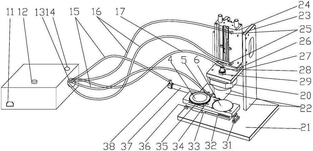
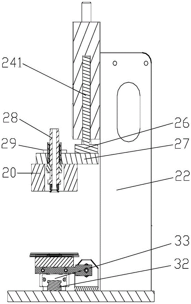
[0034] figure 2 It shows the assembly and pressure holding jig structure according to the embodiment of the present invention; image 3 The side test structure of the assembly and pressure holding fixture according to the embodiment of the present invention is shown.

[0035] Such as figure 2 and image 3 Commonly shown, the assembly and pressure-holding jig of the embodiment of the present invention includes a suction nozzle 28, a fixed tooling 35, a base plate 21, an electrical control box, and a first cylinder 24 connected to the electrical control box; There are support plates 22 (comprising the first support plate and the second support plate), connected and fixed by the cylinder connection plate 23 between each support plate 22, the first cy...


PUM


Abstract

The invention provides an assembling and pressure maintaining jig. The assembling and pressure maintaining jig comprises an electrical control box, a bottom board and a first cylinder connected with the electric control box. A first supporting board and a second supporting board which are arranged in parallel are fixed to the bottom board. The first supporting board and the second supporting board are connected and fixed through a cylinder connecting board. The first cylinder is fixed to the cylinder connecting board. The assembling and pressure maintaining jig further comprises a suction nozzle and a fixing tool. A cylinder push board is arranged on the first cylinder. A connecting board is arranged below the cylinder push board. A pressing block is fixed below the connecting board and used for maintaining the pressure of bonded workpieces. The suction nozzle is fixed to the connecting board and embedded in the pressing block. The suction nozzle is connected with the electrical control box through a first air pipe and used for sucking the workpieces for transfer. The fixing tool is movably connected with the bottom board. A first workpiece containing groove and a second workpiece containing groove which are matched with the workpieces to be assembled are formed in the fixing tool. By the utilization of the assembling and pressure maintaining jig, production efficiency is high and investment cost is low.

Description

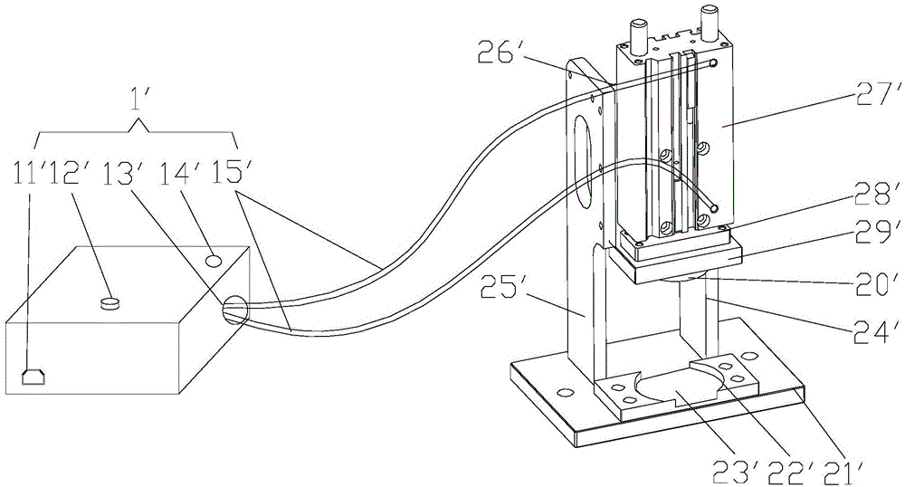
technical field [0001] The invention relates to the technical field of electronic manufacturing, and more specifically, to a fixture for assembling and maintaining pressure of workpieces. Background technique [0002] In the electronic manufacturing industry, the assembly process of products often involves bonding and fixing between parts, and then pressure is applied to the bonded parts to ensure the firmness of the bonding. At present, the common bonding and pressure-holding process is to bond the parts first, and then apply pressure to the upper and lower sides of the pasted whole part, and maintain the pressure for a certain period of time. [0003] specifically, figure 1 It shows the structure of the existing product assembly and pressure holding device. [0004] Such as figure 1 As shown, the existing product assembly and pressure maintaining device includes a base plate 21', a fixed tooling 22', a cylinder 27' and an electrical control box 1' for controlling the ac...

Claims


Application Information

Patent Timeline
Patent Type & Authority Applications(China)
IPC IPC(8): F16B11/00F15B13/02
CPCF15B13/02F16B11/006
Inventor 王世英顾宗伟宋宝忠潘茂峰
Owner GOERTEK INC
Learn More