A transmission mechanism using a climbing rope

A transmission mechanism and rope climbing technology, which is applied in the field of transmission mechanism devices, can solve problems such as burning components, affecting power generation efficiency, and requiring high installation accuracy

Active Publication Date: 2017-05-03
ANHUI TIANZHU GREEN ENERGY SCI & TECH
View PDF9 Cites 0 Cited by
  • Summary
  • Abstract
  • Description
  • Claims
  • Application Information

AI Technical Summary

Problems solved by technology

If dust adheres to the surface of the photovoltaic module, it will affect the light transmittance, and then affect the radiation received by the surface of the module, which will affect the power generation efficiency, and because the distance between the dust and the battery is very close, it will form a shadow, and it will Photovoltaic modules locally form a hot spot effect, which reduces the power generation efficiency of the modules, and even burns the modules. Therefore, keeping the photovoltaic modules clean is an effective way to ensure the maximum power generation capacity of the photovoltaic power station
[0003] Existing photovoltaic module cleaning systems are all driven by wire rope traction. This structure requires high installation accuracy and is troublesome to install.

Method used


Image

  • A transmission mechanism using a climbing rope
  • A transmission mechanism using a climbing rope

Examples


Embodiment Construction

[0013] The invention will be further described below by means of drawings and specific embodiments. The specific embodiments described here are only for explaining the invention, and are not intended to limit the protection scope of the present invention.

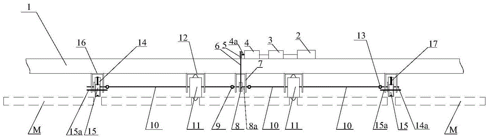
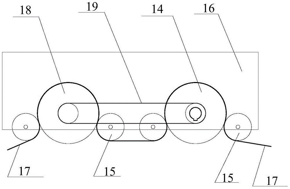
[0014] A transmission mechanism using a climbing rope, such as figure 1 , figure 2 As shown, it includes beam 1, motor 4, driving wheel 5, driven wheel 8, synchronous belt 6, transmission flexible shaft 10 and traction device, motor 4 is electrically connected to controller 3, controller 3 is connected to battery 2, and motor 4 is fixed On the beam 1, the motor shaft 4a is connected with the driving wheel 5, and the driving wheel 5 is connected with the driven wheel 8 through the synchronous belt 6, and the driven wheel 8 is fixed below the beam 1 by the first bracket 7; the two axles 8a of the driven wheel The two flexible shaft joints 9 are respectively connected to the two transmission flexible shafts 10, and the othe...


PUM


Abstract

The invention provides a transmission mechanism with a climbing rope. The transmission mechanism with the climbing rope comprises a cross beam, a motor, a driving wheel, a driven wheel, a synchronizing belt, flexible transmission shafts and traction devices. The motor shaft is connected with the driving wheel which is connected with the driven wheel through the synchronizing belt. The driven wheel is fixed to the position below the cross beam through a first support. Wheel shafts of the driven wheel are connected with the flexible transmission shafts through flexible shaft connectors. The other ends of the flexible transmission shafts are connected with the traction devices. The traction devices are fixed to the position below the cross beam through a second support and each comprises a first drive wheel, a second drive wheel, at least four guide wheels and pulling ropes. The flexible transmission shafts are connected with wheel shafts of the first drive wheels through flexible shaft connectors. Each first drive wheel is connected with the corresponding second drive wheel through the synchronizing belt. Every four guide wheels are distributed on the portions located between the corresponding first drive wheel and the corresponding second drive wheel and located on the two sides of the corresponding first drive wheel and the corresponding second drive wheel. The first drive wheels and the second drive wheels are connected with the adjacent guide wheels through the pulling ropes. The transmission mechanism with the climbing rope is easy to install, guarantees that a brush cleaner will not deviate in operation and prevents a photovoltaic module from being in contact with hard matter and being scratched.

Description

technical field [0001] The invention relates to a transmission mechanism device, in particular to a transmission mechanism using a climbing rope suitable for a photovoltaic module cleaning system. Background technique [0002] Photovoltaic power generation is a clean energy that has been widely used all over the world. Photovoltaic modules are the source of electricity generated by solar power plants, and the efficiency of photovoltaic modules directly determines the power generation of solar power plants. If dust adheres to the surface of the photovoltaic module, it will affect the light transmittance, and then affect the radiation received by the surface of the module, which will affect the power generation efficiency, and because the distance between the dust and the battery is very close, it will form a shadow, and it will Photovoltaic modules locally form a hot spot effect, which reduces the power generation efficiency of the modules, and even burns the modules. Theref...

Claims


Application Information

Patent Timeline
Patent Type & Authority Patents(China)
IPC IPC(8): F16H7/02H02S40/00
CPCF16H7/02H02S40/00Y02E10/50
Inventor 李凤光刘祥卢育发
Owner ANHUI TIANZHU GREEN ENERGY SCI & TECH
Why Eureka
Try Eureka