Self-generating lighting modules and faucets

A lighting module and self-generating technology, applied in the field of faucets, can solve the problems of loosening or shaking of screw joints, damage to lighting equipment, and easy contamination.

Inactive Publication Date: 2018-02-23
GLOBE UNION INDAL
View PDF7 Cites 0 Cited by
  • Summary
  • Abstract
  • Description
  • Claims
  • Application Information

AI Technical Summary

Problems solved by technology

[0003] As mentioned above, micro-hydraulic generators combined with LED circuit boards have been gradually installed and applied to various faucets. This kind of self-generating lighting device that uses the water flow through the faucet to generate electricity to supply the power required by LED lighting, its micro-hydraulic The generator and the LED circuit board are usually installed separately. The common disadvantage of this device is that a special space must be provided inside the faucet for the wiring between the micro-hydraulic generator and the LED circuit board to be accommodated, and the wiring must also be considered. The fixation and ease of installation can avoid water seepage and damage to lighting equipment, and even the risk of leakage. It is also necessary to consider whether the circuit will be twisted or bent during the configuration or operation of the faucet.
[0004] Another common self-generating lighting device mainly installs the micro-hydraulic generator and the LED circuit board together in a box or a water outlet housing, and then installs the box or water outlet housing on the water outlet of the faucet. Therefore, The whole is an external design, although it can avoid the internal space design and circuit configuration problems of the faucet, and the problems of water seepage and leakage are easier to overcome, but for users who pay attention to the consistency of texture, product appearance and integrated aesthetics, the external The traditional design is difficult to accept, and this kind of self-generating lighting device is usually screwed into the water outlet of the faucet, which will cause the water outlet position to be too low, easy to get dirty, and loose at the screw joint after frequent contact and collision. off or shaken

Method used


Image

  • Self-generating lighting modules and faucets
  • Self-generating lighting modules and faucets
  • Self-generating lighting modules and faucets

Examples


Embodiment 1

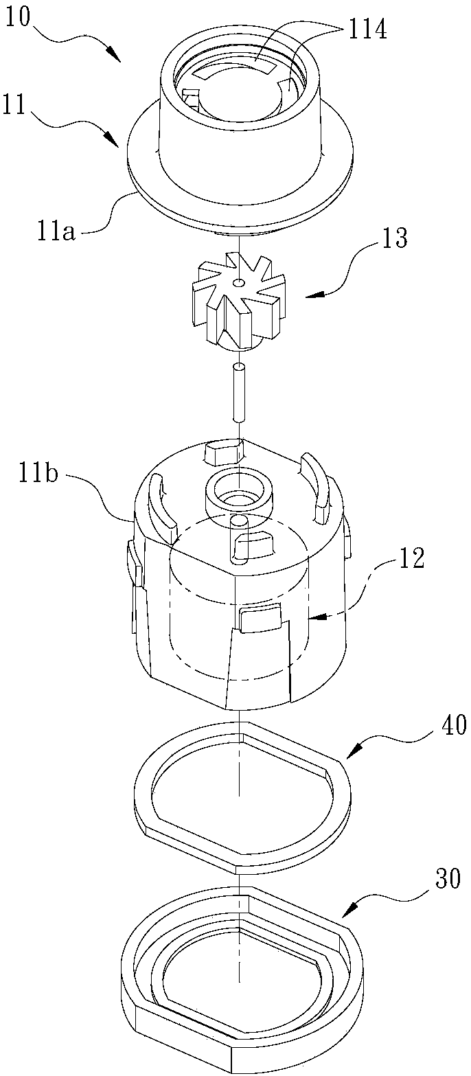
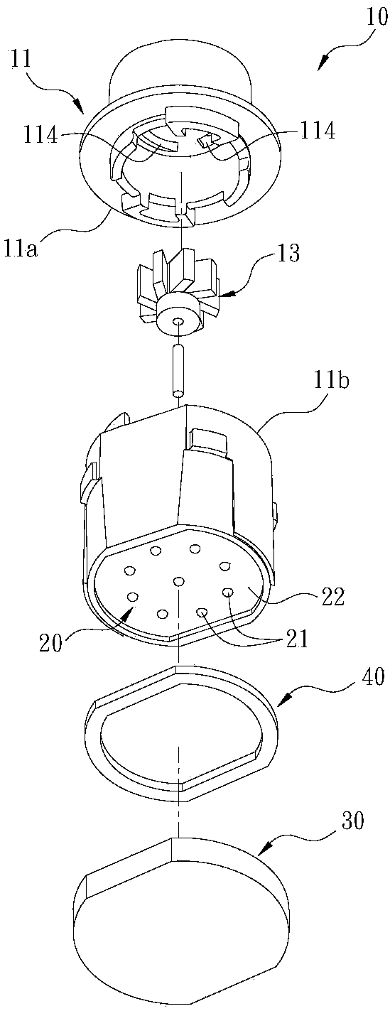
[0084] Such as Figures 1 to 6 As shown, the self-generating lighting module 1 can be installed and positioned in a water outlet channel 2a inside a faucet 2, as Figure 7 , 8 As shown, it mainly includes a micro-hydraulic generator 10 , an LED circuit board 20 and a waterproof seal 30 . The faucet 2 of this embodiment is a common pull-out faucet, especially a pull-out faucet for kitchens. The user can turn on the water outlet or turn off the water stop by pressing the push switch 2b. The following is a separate description of the constituent components of the above-mentioned self-generating lighting module 1 .

[0085] Such as figure 2 , 3 As shown, the micro-hydraulic generator 10 includes a casing 11, a generating unit 12 and an impeller group 13; as Figure 5 , 6 As shown, the casing 11 includes a water part 111 where the impeller set 13 can be installed, and a machine room part 112 where the generator set 12 can be installed; When the water flow of the water flow ...

Embodiment 2

[0101] Such as Figures 10 to 16 As shown, the self-generating lighting module 100 of the invention is roughly the same as the self-generating lighting module 1 of the above-mentioned first embodiment, the main differences are:

[0102] The exterior shapes of the two are slightly different. Therefore, the self-generating lighting module 100 of this embodiment can be installed and applied to different types of faucets, such as non-pull-out faucets 3, such as Figure 17 , 18 Shown, especially for non-pull-out kitchen faucets. The faucet 3 also includes a faucet body 300 , defining a water outlet channel 301 inside, and an installation chamber 302 disposed on the water outlet channel 301 for installing the self-generating lighting module 100 therein. Also include a press switch 303 that can control water outlet and water stop.

[0103] More specifically, if Figure 18 As shown, the push switch 303 of this embodiment is arranged on a light-permeable wall 304 . The LED circuit...


PUM


Abstract

The invention provides a self-generating lighting module and a faucet. The self-generating lighting module can be installed in the water outlet channel of the faucet, and includes a micro-hydraulic generator, an LED circuit board and a waterproof sealing member. When the water flow enters the water outlet channel of the faucet, the micro-hydraulic generator can generate electricity to supply the LED circuit board and the LED on it to emit light. The waterproof seal can seal the LED circuit board to the machine room of the micro-hydraulic generator, and completely isolate it from the water flow, so as to meet the requirements of relevant safety regulations in various countries, and no relevant safety certification is required. At least a part of the waterproof sealing member has light transmittance, through which LED light can pass through, so as to maintain good light transmittance and luminous intensity. The waterproof seal can also be used to change the diversity of light, and it is also helpful to assemble and fix the self-generating lighting module with the faucet, and can change the direction of water flow.

Description

Technical field: [0001] The invention relates to a faucet and its components, in particular to a self-generating lighting module and a faucet equipped with the self-generating lighting module. Background technique: [0002] Many existing patent technical documents have disclosed that lighting components are installed inside the faucet or at the water outlet, so as to provide lighting, light indication, decoration, and make the water flow produce different light changes, and even meet the requirements of energy saving. For example, US Patent No. US 6,774,584B2 discloses that a light source directly irradiates the water flowing from the outlet of the faucet, and the light source is at least two LEDs of different colors. A similar concept is to combine the lighting component with the water wave device, or install it at the outlet of the faucet. In addition to providing the function of illuminating the water flow, it can also be combined with a micro-hydraulic generator, so that...

Claims


Application Information

Patent Timeline
Patent Type & Authority Patents(China)
IPC IPC(8): F21S9/04F21V31/00F21V19/00F03B13/00F16K51/00F21Y115/10
Inventor 袁家骅邱慧玲李俊宏
Owner GLOBE UNION INDAL
Why Eureka
Try Eureka