Two-oil-way three-air-way multi-rotational-flow air atomizing nozzle structure

An air atomization, dual oil circuit technology, applied in the combustion method, liquid fuel supply/distribution, combustion chamber, etc., can solve the problems of high processing technology requirements, uneven temperature distribution, deterioration of fuel atomization quality, etc. The effect of improving combustion efficiency, reducing NOx emissions, and reducing atomization diameter

Active Publication Date: 2015-11-11
INST OF ENGINEERING THERMOPHYSICS - CHINESE ACAD OF SCI
View PDF3 Cites 22 Cited by
  • Summary
  • Abstract
  • Description
  • Claims
  • Application Information

AI Technical Summary

Problems solved by technology

The disadvantage of this kind of air atomizing nozzle is that it requires high processing technology. If the structure of the fuel outlet annular seam is not concentric with the structure of the nozzle body due to some reasons, it

Method used


Image

  • Two-oil-way three-air-way multi-rotational-flow air atomizing nozzle structure
  • Two-oil-way three-air-way multi-rotational-flow air atomizing nozzle structure
  • Two-oil-way three-air-way multi-rotational-flow air atomizing nozzle structure

Examples


Example Embodiment

[0029] In order to make the objectives, technical solutions, and advantages of the present invention clearer, the following further describes the present invention in detail with reference to the accompanying drawings and embodiments.

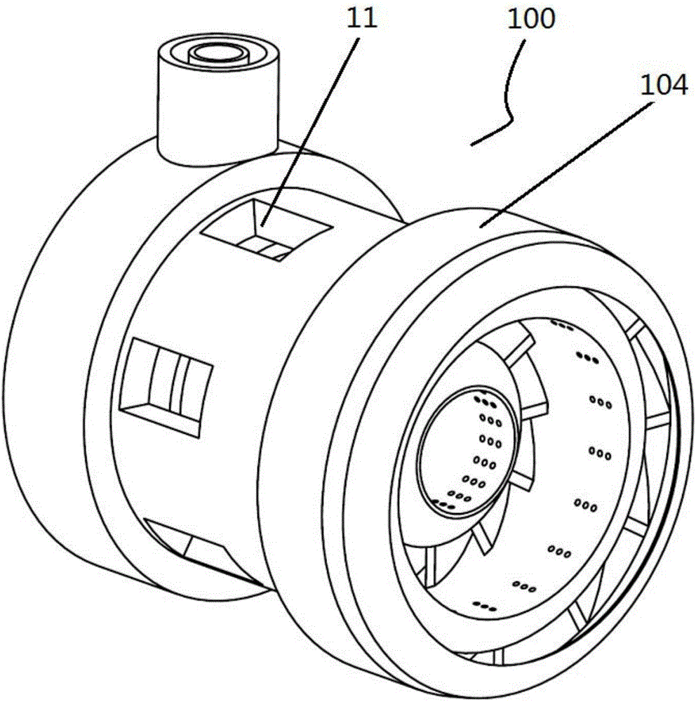
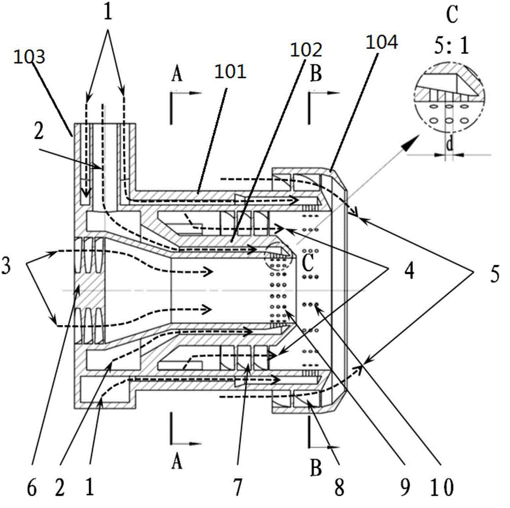
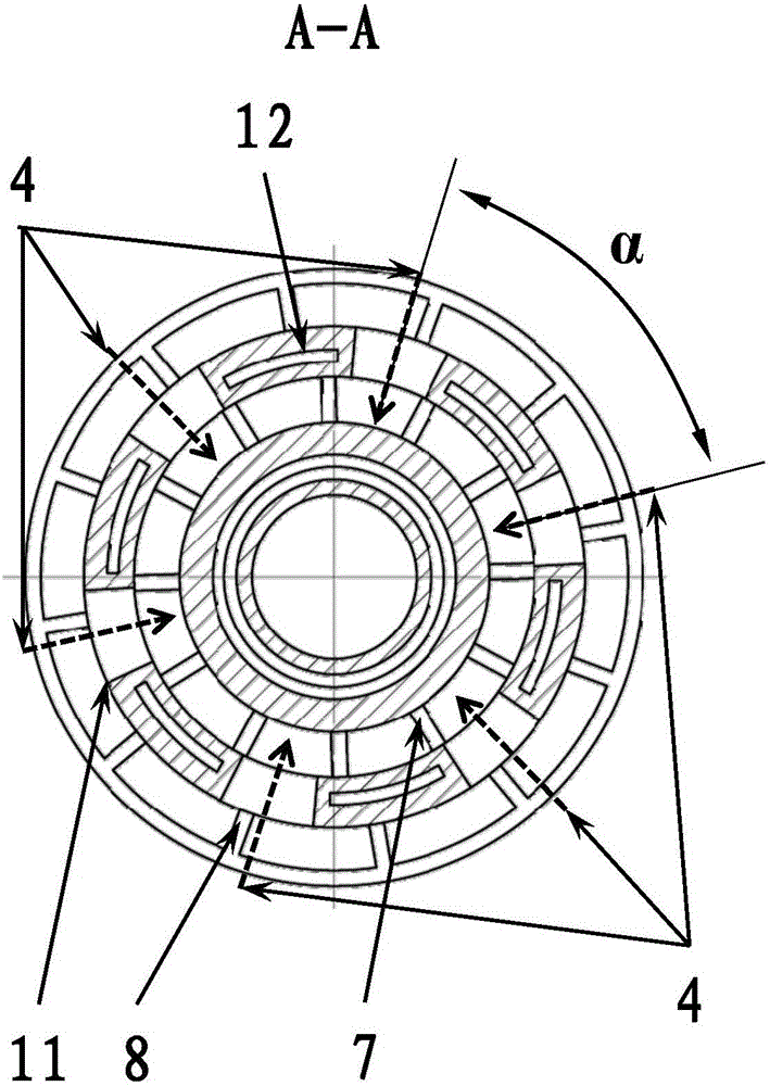
[0030] Such as Figure 1-4 As shown, the dual-oil, three-air, multi-swirl air atomization nozzle structure of the present invention is used to reduce the atomization diameter of liquid fuel, improve the combustion efficiency of the combustion chamber, and reduce NOx emissions; the combustion chamber uses liquid fuel, The air atomizing nozzle includes a nozzle body 100, which is a double-layered cylinder structure, including an outer cylinder 101 with an annular interlayer and an inner cylinder 102 with an annular interlayer. The outer cylinder 101 is composed of an annular interlayer The main oil passage 1, the annular interlayer of the inner cylinder 102 constitutes the auxiliary oil passage 102, the outer cylinder 101 and the inner cylinder 102 ...


PUM

PropertyMeasurementUnit
Diameteraaaaaaaaaa
Angleaaaaaaaaaa

Abstract

The invention relates to a two-oil-way three-air-way multi-rotational-flow air atomizing nozzle structure. The air atomizing nozzle structure is used for reducing the atomizing diameter of liquid fuel and improving the burning efficiency of a burning chamber; axial rotational flow blades are arranged on a first-stage air way, a second-stage air way and a third-stage air way; a main oil way of a fuel oil pipe is communicated with a main oil way of a nozzle through a plurality of sector fuel runners, and an auxiliary oil way of the fuel oil pipe is communicated with an auxiliary oil way of the nozzle; the auxiliary oil way of the nozzle is located between the first-stage air way and the second-stage air way, and the main oil way of the nozzle is located between the second-stage air way and the third-stage air way; the inner wall faces of the tail ends of the main oil way and the auxiliary oil way of the nozzle are provided with a plurality of rows of fuel jetting holes, and the fuel jetting holes are arranged in sequence or in an intersected manner; the rotation directions of the first-stage rotational flow blade and the third-stage rotational flow blade are the same and are opposite to the rotation direction of the second-stage rotational flow blade; and air flow in the first-stage air way and the third-stage air way directly enters the first-stage air way and the third-stage air way of the nozzle in the axial direction, and air flow in the second-stage air way enters the second-stage air way through radial rectangle air inlet holes evenly distributed on the outer wall face of the air atomizing nozzle by a certain angle in the circumferential direction.

Description

technical field [0001] The invention relates to the field of combustion, and is a device for reducing the atomization diameter of liquid fuel, improving the combustion efficiency of a combustion chamber, and reducing NOx emissions. Nozzle structure. Background technique [0002] The fuel atomization diameter has a crucial influence on the combustion performance of the gas turbine combustor. Before the liquid fuel enters the gas turbine combustor for combustion, it undergoes a process of atomization and then evaporation. Reducing the atomization diameter of the liquid fuel can effectively reduce the fuel consumption. The evaporation time and chemical reaction time are shortened, so as to achieve the purpose of enhancing the combustion efficiency of the combustion chamber and optimizing the outlet temperature distribution. For gas turbines on military aircraft, reducing the atomization diameter of liquid fuel can effectively shorten the axial length of the gas turbine combust...

Claims


Application Information

Patent Timeline
IPC IPC(8): F23R3/38F23K5/14
CPCF23R3/286
Inventor 胡斌赵庆军孙小磊崔伟伟徐建中
Owner INST OF ENGINEERING THERMOPHYSICS - CHINESE ACAD OF SCI
Why Eureka
Try Eureka