Hydraulic transmission pressure gauge

A technology of hydraulic transmission and pressure gauge, applied in the direction of piston fluid pressure measurement, etc., can solve the problems of increased production cost, complicated processing, difficult production, etc., and achieve the effect of reduced production cost, less coordination relationship, and easy processing and production

Inactive Publication Date: 2015-11-11
CHONGQING BRIGHTY INSTR
View PDF1 Cites 10 Cited by
  • Summary
  • Abstract
  • Description
  • Claims
  • Application Information

AI Technical Summary

Problems solved by technology

Although the structure of the pressure gauge of this structure is simple, when the transmission rod is processed, it can be constrained in the case and rotate around its own axis. It must be specially treated, or more parts must be manufactured to ensure its function. In the process of processing guide holes and threads, the processing is complicated, production is difficult, and production costs are increased

Method used


Image

  • Hydraulic transmission pressure gauge

Examples


Embodiment Construction

[0013] The present invention will be described in further detail below by means of specific embodiments:

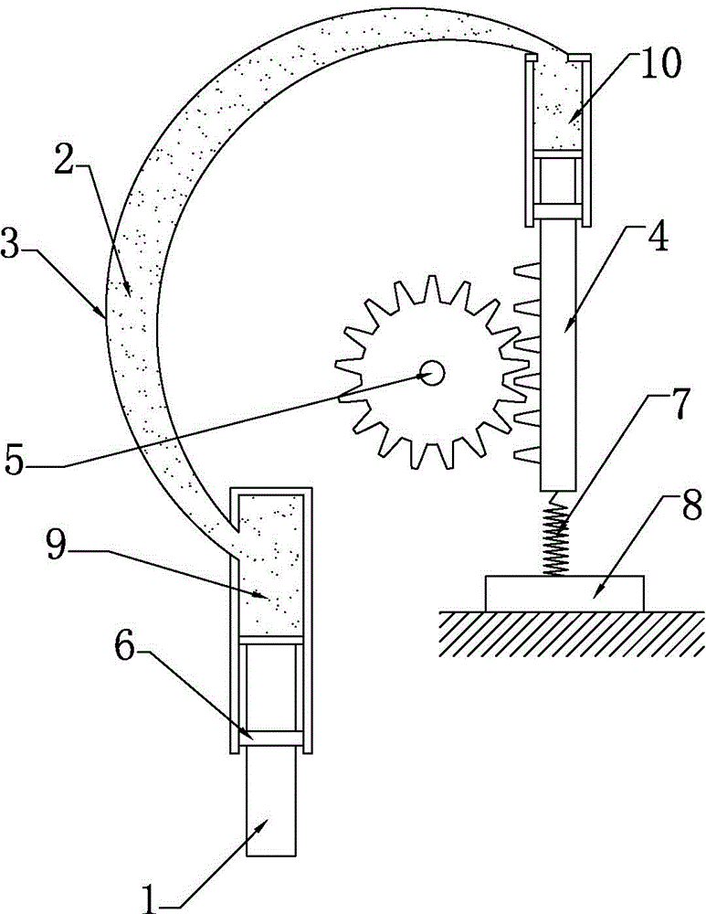
[0014] The reference signs in the drawings of the description include: piston 1, butter 2, hollow tube 3, rack 4, gear 5, sealing ring 6, spring 7, fixed rod 8, first cavity 9, second cavity 10 .

[0015] The embodiment is basically as attached figure 1 As shown: a hydraulic transmission pressure gauge, including a hollow tube 3, the hollow tube 3 is an arc-shaped hollow tube 3, the hollow tube 3 is provided with butter 2, and the first cavity 9 at one end of the hollow tube 3 A vertical piston 1 is slidably connected, the piston 1 communicates with the inlet of the pressure gauge, a vertical rack 4 is slidably connected in the second cavity 10 at the other end of the hollow tube 3, and the first cavity 9 is set Below the second cavity 10, the size of the first cavity 9 is greater than the size of the second cavity 10, the lower side of the rack 4 is provided with a fix...


PUM


Abstract

The invention discloses a hydraulic transmission pressure gauge. The hydraulic transmission pressure gauge includes a hollow tube; hydraulic oil is arranged in the hollow tube; a piston is connected into a first cavity at one end of the hollow tube in a sliding manner; the piston is communicated with the inlet of the pressure gauge; a rack is connected into a second cavity at the other end of the hollow tube in a sliding manner; one side of the rack, which is far away from the second cavity, is provided with a fixing rod; a spring is connected between the rack and the fixing rod; the rack is engaged with a gear; and the gear is fixedly connected with a pointer. The hydraulic transmission pressure gauge of the invention has the advantages of simple structure and lower production cost.

Description

technical field [0001] The invention relates to a pressure gauge, in particular to a hydraulic transmission pressure gauge. Background technique [0002] A pressure gauge is an instrument that uses elastic elements as sensitive elements to measure and indicate pressure higher than the environment. It is widely used, and it pervades almost all industrial processes and scientific research fields. It can be seen everywhere in the fields of heat pipe network, oil and gas transmission, water supply and gas supply system, vehicle maintenance shop, etc., especially in the process of industrial process control and technical measurement, because the elastic sensitive element of the mechanical pressure gauge has high mechanical strength and The characteristics of convenient production make mechanical pressure gauges more and more widely used. [0003] The Chinese patent number is CN201410344095.9, which discloses a pressure gauge, including a watch case, a dial, a pointer, and a conv...

Claims


Application Information

Patent Timeline
IPC IPC(8): G01L7/16
Inventor 王军
Owner CHONGQING BRIGHTY INSTR
Why Eureka
Try Eureka