Ball valve gas tightness test apparatus

A technology for air tightness testing and ball valves, which is applied in the direction of liquid tightness measurement using liquid/vacuum, manufacturing tools, workpiece clamping devices, etc. It can solve problems such as uneven end faces of ball valves, complicated operation processes, and troublesome installation of ball valves. , to achieve a reasonable overall structure, strengthen the sealing effect, and improve the sealing effect

Inactive Publication Date: 2015-11-11
王国良
View PDF8 Cites 16 Cited by
  • Summary
  • Abstract
  • Description
  • Claims
  • Application Information

AI Technical Summary

Problems solved by technology

[0004] The above-mentioned test method has the following disadvantages: 1. The operation process is complicated, and the weight of the frame is relatively heavy. It is necessary to immerse the frame in water with the help of external equipment, and the installation of the ball valve is also relatively troublesome; 2. The ball valve is sealed by pressing down the plate with a jack And when the sealing ring is placed outside the two ends of the ball valve and clamped on both ends of the ball valve by a hydraulic cylinder for sealing, the strength of both is difficult to control. The seal of the part is not reliable, which will affect the accuracy of the test and cause misjudgment of quality. If the force of pressing down or clamping is excessive, the ball valve will be deformed, causing the end surface (pipe end) of the ball valve to be uneven, thus making the ball valve It cannot form a seal with the pressure plate, which will lead to misjudgment of quality. In addition, if the force of pressing down or clamping is excessive, the ball valve may be directly damaged

Method used


Image

  • Ball valve gas tightness test apparatus
  • Ball valve gas tightness test apparatus
  • Ball valve gas tightness test apparatus

Examples


Embodiment 1

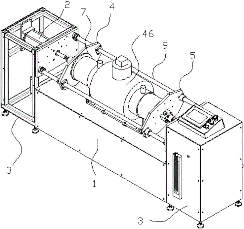
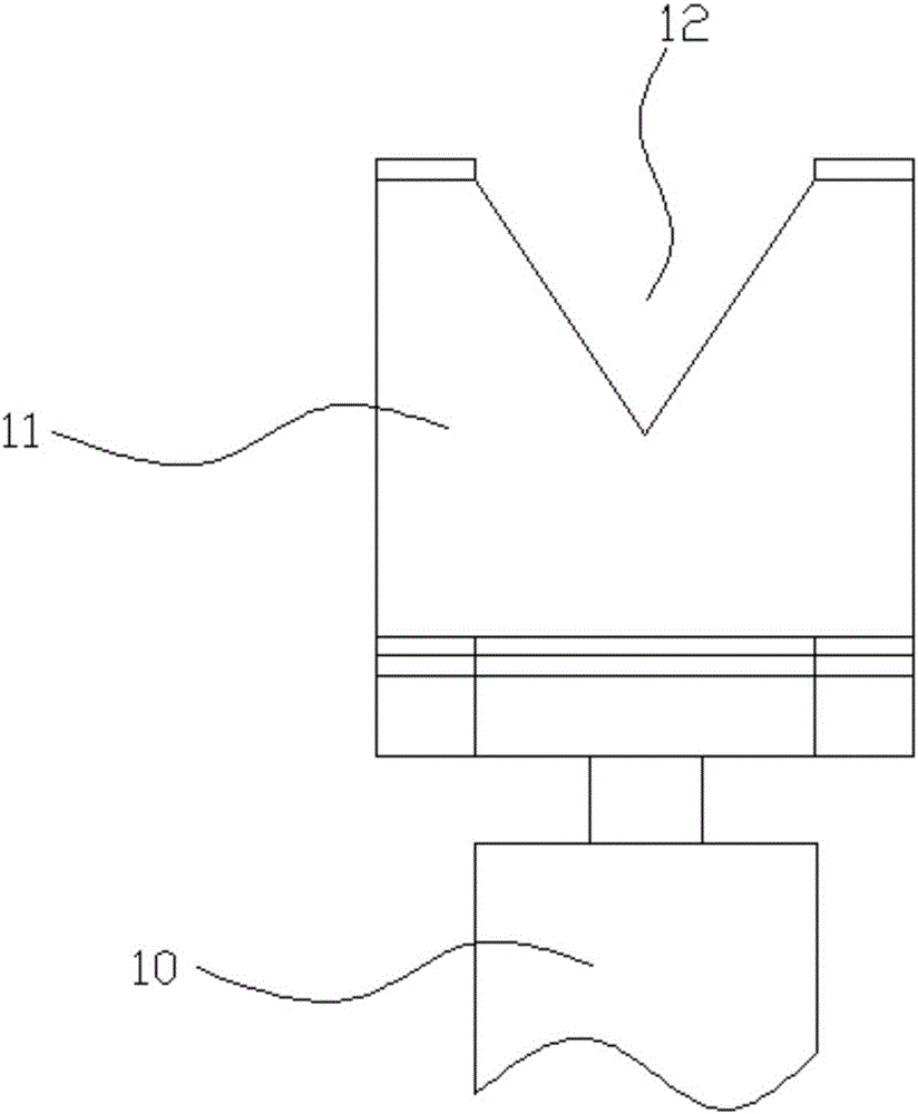
[0038] Embodiment 1: as Figure 1 to Figure 4 In the shown embodiment, a ball valve airtightness testing device includes an air supply pump, an air pressure sensor 14, a main frame 1, two push plate cylinders 2, two side frames 3 with opposite inner sides, and a main end cover 4 , auxiliary end cover 5, the main end cover and the auxiliary end cover are parallel to each other, the main frame is provided with a ball valve support frame 6 for supporting the ball valve to be tested, and two push plate cylinders are respectively located on the two side machine On the frame, the piston rod of one push pedal cylinder is connected to the main end cover, and the piston rod of the other push pedal cylinder is connected to the auxiliary end cover. The surface of the main end cover near the ball valve support frame is provided with a contact The main elastic sealing ring pad 7 at the pipe end of the ball valve to be tested, the surface of the secondary end cover close to the ball valve s...

Embodiment 2

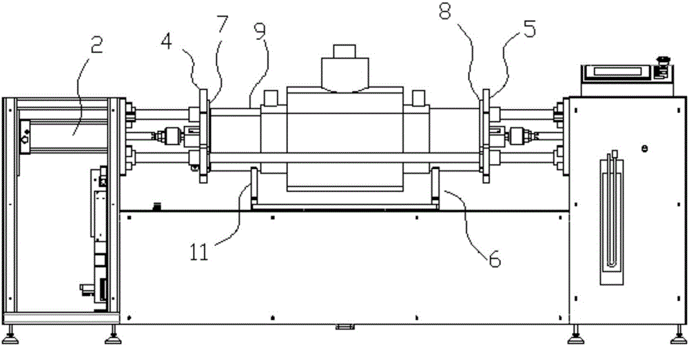
[0040] Embodiment 2: as Figure 5 to Figure 7 In the shown embodiment, a ball valve air tightness testing equipment includes an air supply pump 13, an air pressure sensor, a main frame, two push plate cylinders, two side frames with opposite inner surfaces, a main end cover, and a secondary end cover , the main end cover and the auxiliary end cover are parallel to each other, the main frame is provided with a ball valve support frame for supporting the ball valve to be tested, and two push plate cylinders are respectively arranged on the two side frames, one of which pushes The piston rod of the plate cylinder is connected to the main end cover, and the piston rod of the other push plate cylinder is connected to the auxiliary end cover. Elastic sealing ring pad 7, the surface of the auxiliary end cover close to the ball valve support frame side is provided with an auxiliary elastic sealing ring plate 8 for contacting the pipe end of the ball valve to be tested, and the main en...

Embodiment 3

[0048] Embodiment 3: the basic structure and implementation mode of this embodiment are the same as embodiment 2, and its difference is, as Figure 8 to Figure 11 As shown in: It also includes two anti-retraction cylinders 31, one of which is fixed on the main end cover through an anti-retraction bracket 32, and the other anti-retraction cylinder is fixed on the secondary end cover through an anti-retraction bracket , the anti-retraction cylinder is provided with a push plate piston 33 that can slide up and down in the anti-retraction cylinder, the described push plate piston is connected with the inner end of a disc piston rod 34, and the outer end of the disc piston rod is provided with There is a suction cup 35, and the described connecting disk piston rod is vertical, and the described pushing disk piston divides the anti-retraction cylinder where it is located into an air chamber 36 and an active chamber 37, and the described inflatable chamber is connected with an anti-re...


PUM


Abstract

The invention discloses a ball valve gas tightness test apparatus. The ball valve gas tightness test apparatus has the advantages of convenient operation and high accuracy. With the ball valve gas tightness test apparatus adopted, it can be ensured that two end pipes of a ball valve have little possibility of being damaged due to clamping. The ball valve gas tightness test apparatus includes an air feed pump, a pressure sensor, a main rack, two push plate air cylinders, two side racks, a main end cover and an auxiliary end cover; the two push plate air cylinders are respectively located on the two side racks; the piston rod of one of the push plate air cylinders is connected with the main end cover; the piston rod of the other push plate air cylinder is connected with the auxiliary end cover; the main end cover is provided with a main elastic sealing ring gasket; the auxiliary end cover is provided with an auxiliary elastic sealing ring gasket; and a main cover air hole is formed in the main end cover. With the ball valve gas tightness test apparatus of the invention adopted, a ball valve can be positioned and clamped in place, and gas tightness can be ensured, and at the same time, the ball valve will not be damaged due to clamping. The ball valve gas tightness test apparatus has an adaptively-adjustable sealing structure, so that a sealing effect in high-air pressure detection can be strengthened; the ball valve gas tightness test apparatus has an auxiliary positioning structure, the rollback of the end covers can be avoided, and the push plate air cylinders can be protected, and a sealing effect can be improved, and stability in a detection process can be maintained.

Description

technical field [0001] The invention belongs to the technical field of ball valve air tightness testing, in particular to a ball valve air tightness testing equipment. Background technique [0002] Ball valves are commonly used opening and closing parts for gas or liquid circulation. They are used in different occasions and have different sealing requirements. Therefore, they need to be tested for sealing before leaving the factory, otherwise there will be greater safety hazards. [0003] In the prior art, when testing a ball valve, a gasket or a sealing ring is usually placed on the outside of both ends of the ball valve, and at the same time, a force-applying device such as a jack or a hydraulic cylinder is used to clamp the two ends of the ball valve, so that the gasket or sealing ring and the ball valve are two The end is sealed, and the whole sealed ball valve is immersed in water, and then compressed gas is passed into the ball valve to test its sealing performance. ...

Claims


Application Information

Patent Timeline
Patent Type & Authority Applications(China)
IPC IPC(8): G01M3/02B25B11/00
Inventor 王国良王楠
Owner 王国良
Why Eureka
Try Eureka