Fire test furnace loading device

A technology of fire test furnace and loading device, which is applied in the direction of measuring device, applying stable tension/pressure to test the strength of materials, instruments, etc., which can solve problems such as the influence of test results, so as to ensure the strength and stability of the supporting structure and improve the results The effect of accuracy

Inactive Publication Date: 2015-11-11
ANHUI UNIVERSITY OF ARCHITECTURE
View PDF5 Cites 15 Cited by
  • Summary
  • Abstract
  • Description
  • Claims
  • Application Information

AI Technical Summary

Problems solved by technology

The disadvantage is that this kind of loading device can only apply vertical load or lateral load alone
In the actual fire, there is not only one-way load, so only one-way load has a great influence on the test results

Method used


Image

  • Fire test furnace loading device
  • Fire test furnace loading device
  • Fire test furnace loading device

Examples


Embodiment 1

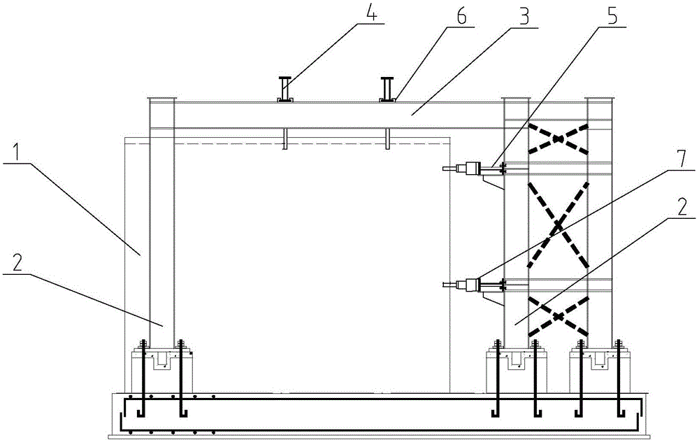
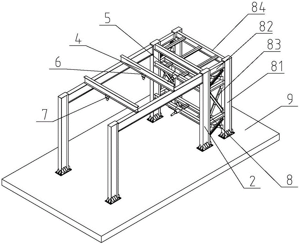
[0035] In this embodiment, the other side of the horizontal loading beam 5 is provided with a truss steel structure 8 connected with vertically adjacent columns 2 . The purpose is to improve the strength and stability of the supporting structure of the whole loading device. Specifically, the truss steel structure 8 includes steel columns 81 that are the same height as the columns 2 and are arranged parallel to and spaced apart from the columns 2. At least two short steel beams 82 are connected between the horizontally adjacent steel columns 81 and the columns 2. A support rod 83 is obliquely connected to the diagonal of the short steel beam 82 , and a long steel beam 84 is connected between the steel column 81 and the steel column 81 . The truss steel structure 8 adopting this structure has the advantages of high structural strength, strong stability, non-deformation and small occupied volume compared with the commonly used reaction frame loading frame in the past. In order t...

Embodiment 2

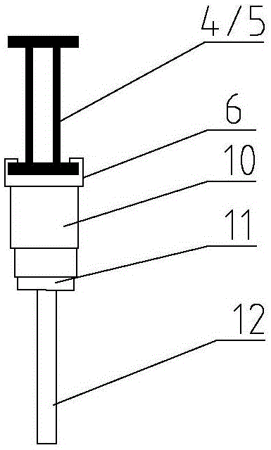
[0037] In this embodiment, the detection device 7 is a telescopic sensor detection mechanism, see image 3 , the telescopic sensing and detection mechanism includes an electro-hydraulic jack 10, the end face of the cylinder of the electro-hydraulic jack 10 is connected to the bottom of the slider 6, the end face of the piston at the other end is connected to the sensor 11, and the other end of the sensor 11 is connected to a high temperature resistant tungsten steel Connecting rod 12.

[0038] During use, utilize the expansion and contraction of electrohydraulic jack 10 pistons to apply force (because the slide block 6 that electrohydraulic jack 10 is connected is arranged on vertical loading beam 4 and horizontal loading beam 5, so can realize vertical and Lateral loading.) The effect of simulating multi-faceted force can be achieved on different faces of the component to be tested. The purpose of using high-temperature-resistant tungsten steel connecting rod 12 is that due ...

Embodiment 3

[0043] The slide block 6 is fixed on the vertical loading beam 4 and the horizontal loading beam 5 by fasteners. The purpose is to further limit the loading position of the loading front part and prevent the slide block 6 from being unable to be positioned accurately and stably due to failure of the power mechanism, resulting in failure of the test.


PUM


Abstract

The invention discloses a fire test furnace loading device which comprises stand columns located at four corners of a fire test furnace. Beams are connected between the stand columns transversely adjacent respectively. At least one vertical loading beam is vertically connected between the beams. At least one horizontal loading beam is vertically connected between the stand columns longitudinally adjacent. The vertical loading beams and the horizontal loading beams are each provided with sliding blocks facing the fire test furnace. The sliding blocks have freedom degrees allowing the sliding blocks to move in the length direction of the vertical loading beams and the length direction of the horizontal loading beams. Detecting devices used for detecting performance of members, to be detected, in the fire test furnace are arranged at the bottoms of the sliding blocks. As the vertical loading beams, the horizontal loading beams and the sliding blocks capable of moving in the length direction of the vertical loading beams and the length direction of the horizontal loading beams are utilized, the requirements for vertical loads and transverse loads of the loading device can be met individually or together, the result accuracy of fire tests of a building structure is improved, and convenience of test operation is improved.

Description

technical field [0001] The invention relates to a fire test furnace, in particular to a fire test furnace loading device. Background technique [0002] When studying the building structure system, it is necessary to use the fire experimental furnace to study the stability, firmness and reliability of the building structure under fire and high temperature. This requires that the fire experimental furnace must have a stable and scientific loading device to meet the experimental needs. [0003] The fire test furnace loading device in the prior art usually consists of a reaction force frame fixed on the ground and a jack installed on the upper beam of the reaction force frame (or on the side column of the reaction force frame). The disadvantage is that this kind of loading device can only apply vertical load or lateral load alone. In the actual fire, there is not only one-way load, so only one-way load has a great influence on the test results. Contents of the invention [...

Claims


Application Information

Patent Timeline
Patent Type & Authority Applications(China)
IPC IPC(8): G01N3/02G01N3/18
Inventor 孙强于鑫鑫马巍郝英奇孙晓庄
Owner ANHUI UNIVERSITY OF ARCHITECTURE
Why Eureka
Try Eureka