
Optical fiber contact member part

A technology of optical fiber contact and contact piece, which is applied in the direction of optical components, light guides, optics, etc., can solve the problems affecting the transmission of optical signals, etc., and achieve the effect of convenient assembly and good neutrality

Active Publication Date: 2015-11-11
CHINA AVIATION OPTICAL-ELECTRICAL TECH CO LTD
View PDF5 Cites 16 Cited by
  • Summary
  • Abstract
  • Description
  • Claims
  • Application Information

AI Technical Summary

Problems solved by technology

[0004] The purpose of the present invention is to provide an optical fiber contact part in which the butt joint retaining spring is free from other external forces, which solves the problem that the butt joint retaining spring on the optical fiber contact is subject to other forces in the prior art, which seriously affects the transmission of optical signals

Method used


Image

  • Optical fiber contact member part
  • Optical fiber contact member part
  • Optical fiber contact member part

Examples


Embodiment 1

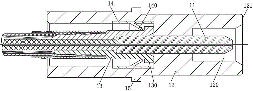
[0018] Embodiment 1 of the fiber optic contact part of the present invention: Since the fiber optic contact is used in conjunction with an adapted fiber optic contact part, for the convenience of description and understanding, the following describes the fiber optic contact part of the present invention and The contact parts that are compatible with the optical fiber contact parts of the present invention are described separately, and the process of plugging and using the two is described. In order to facilitate the distinction, the fiber optic contact parts of the present invention are named as female end contact parts below. , and the contact part suitable for the contact part of the present invention is named as the male end contact part:

[0019] The structure of the receptacle contact part of the present invention is as follows figure 1As shown, it includes the female end contact body and the female end positioning shell arranged outside the female end contact body. The f...


PUM


Abstract

The invention provides an optical fiber contact member part comprising a contact member body which extends in a left-and-right direction. The contact member body is externally provided with a positioning shell. The positioning shell is fixedly provided with an abutting stop guide structure used for left-and-right penetration of the contact member body in a left-and-right direction relatively. The butting maintenance spring affects between the abutting stop guide structure and the contact member body. The positioning shell is provided with a positioning shell blocking surface of which the blocking direction is rightward. The contact member body is provided with a contact member blocking surface which is matched with the positioning shell blocking surface in a blocking way. The positioning shell is also provided with a right positioning surface which is used for being matched with a left positioning surface arranged on the positioning shell of a contact member part adaptive to the optical fiber contact member part in the blocking way at the plugging position. When the optical fiber contact member part is used, amount of compression of the butting maintenance spring is ensured to be maintained within the set range so that great butting of the two adaptive contact member parts can be guaranteed and the effect of optical signal transmission can be enhanced.

Description

technical field [0001] The present invention relates to light guide elements, and more particularly to an optical fiber contact component. Background technique [0002] With the development of network communication, optical fiber plug-in components, as an important part of optical signal transmission, have been more and more widely used. Optical fiber plug-in components generally include a male end contact and a female end contact. For example, a Chinese invention patent with the authorized announcement number CN204331094U and the authorized announcement date of 2015.05.13 discloses an optical fiber contact. This optical fiber contact is actually a A female end contact, including a sleeve, a pin that is a female end pin and an inner sleeve that is a female end sheath. The rear end of the female end sheath is connected to the optical cable, and the tail of the female end sheath is equipped with a spring. It is used to provide elastic force for the female end pin to make the ...

Claims


Application Information

Patent Timeline
IPC IPC(8): G02B6/38
CPCG02B6/3821
Inventor 陈继利
Owner CHINA AVIATION OPTICAL-ELECTRICAL TECH CO LTD
Learn More