Collimation instrument for lens detection

A collimation and lens technology, applied in the field of testing equipment, can solve problems such as ignoring assembly quality, low yield, and poor product consistency, and achieve the effect of improving equipment use efficiency and simple structure

Inactive Publication Date: 2015-11-11
江苏艺佳精密仪器制造有限公司
View PDF0 Cites 1 Cited by
  • Summary
  • Abstract
  • Description
  • Claims
  • Application Information

AI Technical Summary

Problems solved by technology

[0002] Camera lens components, astronomical optical telescope lens components, and other scientific optical instruments are widely used in civil and military fields as high-precision products, so their accuracy directly affects the quality of test data and recorded image data. Optical components It is divided into the lens part and the bracket part, and many companies m

Method used


Image

  • Collimation instrument for lens detection
  • Collimation instrument for lens detection

Examples


Example Embodiment

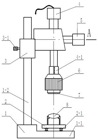
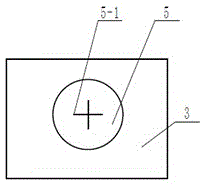
[0012] Depend on figure 1 , figure 2 It is known that a collimator for lens detection is composed of a main bracket 1, a main bracket platform 1-1, a main bracket column 1-2, a storage platform 2, a leg 2-1, a sub bracket 3, and an adjustment knob 3 -1. The light source 4, the scale 4-1, the observation port 5, the cross center line 5-1, the focuser 6, the eyepiece 7, and the lens assembly 8 are composed. The storage platform 2 is fixed on the main support platform 1-1, The auxiliary support 3 is installed on the main support column 1-2, the light source 4 is installed at the upper position of the auxiliary support 3 and penetrates through the auxiliary support 3, the observation port 5 is set at the right end position of the auxiliary support 3 and intersects with the light source 4, and the focus is adjusted. The instrument 6 is installed at the lower end of the light source 4, and the eyepiece 7 is connected with the focusing instrument 6. When working, first adjust the l...


PUM


Abstract

A collimation instrument for lens detection is composed of a main bracket (1), an object placing platform (2), an auxiliary bracket (3), a light source (4), an observation opening (5), a focusing instrument (6), an eyepiece (7), and a lens component (8). The light source (4) is mounted above the auxiliary bracket (3), and penetrates through the auxiliary bracket (3). The observation opening (5) is arranged at the right end of the auxiliary bracket (3), and intersects with the light source (4). The eyepiece (7) and the focusing instrument (6) are connected together. The collimation instrument for lens detection is characterized in that the main bracket (1) is composed of a main bracket platform (1-1) and a main bracket column (1-2), and the center line of the main bracket column (1-2) and the upper surface of the main bracket platform (1-1) form an included angle of 90 degrees. By using an adjusting knob and the focusing instrument to adjust the distance between the eyepiece and a detected product and the focal length, products of different focal lengths and sizes can be detected, and therefore, the utilization efficiency of the equipment is improved.

Description

technical field [0001] The invention relates to the field of detection equipment, in particular to a collimator for lens detection. Background technique [0002] Camera lens assemblies, astronomical optical telescope lens assemblies, and other scientific optical instruments are widely used as high-precision products in civil and military fields, so their accuracy directly affects the quality of test data and recorded image data. Optical components It is divided into the lens part and the bracket part, and many companies manufacture the optical part and the lens part separately, as long as the processing accuracy of their products is guaranteed, and the actual assembly quality after assembly is ignored, so many manufacturers encounter problems in the production and assembly process. To many assembly problems, resulting in poor product consistency, low yield and other issues. Therefore, in order to solve these problems encountered in actual production, it is necessary to adju...

Claims


Application Information

Patent Timeline
IPC IPC(8): G02B27/30
Inventor 唐秋燕
Owner 江苏艺佳精密仪器制造有限公司
Why Eureka
Try Eureka