
A kind of touch display panel and display device

A technology of touch display panel and touch drive, which is applied in the fields of optics, instrumentation, electrical digital data processing, etc., and can solve problems such as easily causing noise, affecting display function, and low signal-to-noise ratio

Active Publication Date: 2016-08-24
CHONGQING BOE OPTOELECTRONICS +1
View PDF3 Cites 0 Cited by
  • Summary
  • Abstract
  • Description
  • Claims
  • Application Information

AI Technical Summary

Problems solved by technology

In a small-sized touch display panel, the common electrode layer formed by Indium Tin Oxide (ITO) material is usually divided into touch driving electrodes and touch sensing electrodes on the array substrate. The touch drive electrodes and touch sense electrodes are electrically connected to the corresponding metal traces through via holes, so that when the liquid crystal deflects, it will easily cause noise, and in order to reduce the impact on the display, a low voltage drive is generally used. Therefore, the overall low signal to noise ratio
If this solution is applied to medium and large-sized touch display panels, due to the large ITO resistance and the low-voltage drive, the signal-to-noise ratio will be lower and the touch function will be affected. If the drive voltage is increased, the display function will be affected. Therefore, This solution is not suitable for medium and large size touch screens

Method used


Image

  • A kind of touch display panel and display device
  • A kind of touch display panel and display device
  • A kind of touch display panel and display device

Examples


Embodiment approach

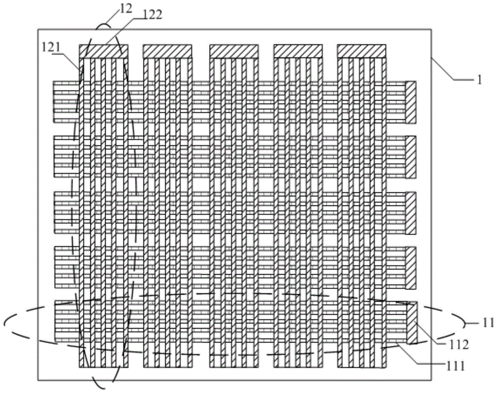
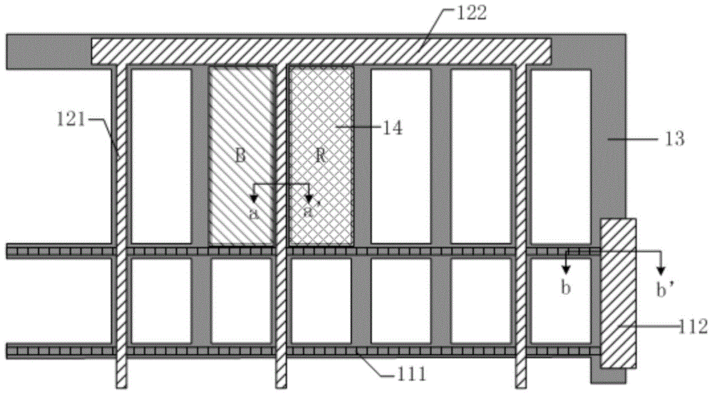
[0049] Specifically, in the first embodiment, such as Figure 5a As shown, part of the touch driving lines 21 and part of the touch sensing lines 22 are arranged on the same layer as the gate, and the rest of the touch driving lines 21 and the rest of the touch sensing lines 22 are arranged on the same layer as the source and drain. At this time, the gate There is an insulating layer 5 between the electrode and the source and drain, and a passivation layer 6 above the source and drain.

[0050] Specifically, in the second embodiment, as Figure 5b As shown, all the touch driving lines 21 are arranged on the same layer as the gate, and all the touch sensing lines 22 are arranged on the same layer as the source and drain. At this time, there is an insulating layer 5 between the gate and the source and drain, and the source and drain There is a passivation layer 6 above the pole.

[0051] Specifically, in the third embodiment, such as Figure 5b As shown, all touch sensing lin...


PUM


Abstract

The invention discloses a touch display panel and a display device. The touch display panel comprises a colored film substrate, an array substrate and a liquid crystal layer positioned between the colored film substrate and the array substrate; the colored film substrate is provided with a plurality of touch driving electrodes arranged along a first direction, and a plurality of touch induction electrodes arranged along a second direction vertical to the first direction; each touch driving electrode comprises a plurality of touch driving sub-electrodes formed by metal materials, and each touch induction electrode comprises a plurality of touch induction sub-electrodes formed by the metal materials, wherein the touch driving sub-electrodes and the touch induction sub-electrodes are mutually independent; the plurality of touch driving sub-electrodes are connected in parallel through first terminal blocks; and the plurality of touch induction sub-electrodes are connected in parallel through second terminal blocks. Only a two-time composition technology needs to be added on the colored film substrate to form the touch driving electrodes and the touch induction electrodes, so that the touch display panel has the advantages of being simple in technology and easy in implementation. In addition, since the electrode materials are the metal materials, the resistance of an electrode can be effectively lowered, and the electrode is suitable for applying to a middle and large size touch display panels.

Description

technical field [0001] The invention relates to the field of display technology, in particular to a touch display panel and a display device. Background technique [0002] At present, with the development of display technology, display technology is widely used in televisions, mobile phones and display of public information. Medium and large size display panels have gradually become a relatively important part of people's lives. At the same time, with the rapid development of display technology, touch screen ( Touch Screen Panel) has gradually pervaded people's lives. Today, in the pursuit of excellent experience functions, touch performance has always been a major defect of medium and large-sized display panels, either limited by technology or limited by cost. [0003] At present, there are mainly three types of embedded touch panels: resistive touch panels, capacitive touch panels, and optical touch panels. The corresponding embedded touch technology has been initially app...

Claims


Application Information

Patent Timeline
Patent Type & Authority Patents(China)
IPC IPC(8): G06F3/041G02F1/1333
Inventor 颜京龙蒋日坤
Owner CHONGQING BOE OPTOELECTRONICS
Learn More