Graphics processing systems

A technology for graphics processing and geometric shapes, applied in the field of graphics processing systems, it can solve the problem of expensive shadows, and achieve the effect of reducing memory and bandwidth

Active Publication Date: 2015-11-11
ARM LTD
View PDF2 Cites 9 Cited by
  • Summary
  • Abstract
  • Description
  • Claims
  • Application Information

AI Technical Summary

Problems solved by technology

[0006] However, shadow volumes can also become very expensive when (for example) considering multiple lights and / or area lights

Method used


Image

  • Graphics processing systems
  • Graphics processing systems
  • Graphics processing systems

Examples


Embodiment Construction

[0138] The preferred embodiment of the present invention will now be described in the context of computer graphics processing for display.

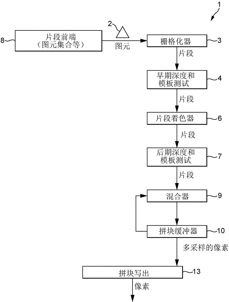
[0139] As known in the art, and as described above, when a computer graphics image is to be displayed, it is usually first defined as a series of primitives (polygons), which are then divided into (rasterized) graphics Fragments are used for sequential graphics rendering. During normal graphics rendering operations, the renderer will modify (for example) the color (red, green, and blue, RGB) and transparency (α) data associated with each fragment so that the fragment can be displayed correctly. Once the fragments pass the renderer completely, their associated data is stored in memory, ready for output for display.

[0140] figure 1 The graphics processing pipeline 1 operating in accordance with the present invention is schematically shown. The graphics processing pipeline 1 is a collage deferred renderer with a fully programmable GPGPU envir...


PUM


Abstract

To simulate the effect of shadows in an image being rendered a light source bounding frustum is produced for a tile for a light source, and used to determine a set of geometry for the tile that could cast a shadow in the tile. The determined set of geometry is then used to determine a light source visibility parameter for each sampling position in the tile by determining for each tile screen space sampling position, whether rays cast between the tile sampling position and a set of sampling positions representing the light source would intersect occluding geometry or not. The determined number of visible light source sampling positions for each tile sampling position is used to determine a light source visibility parameter value for each tile sampling position, and the determined light source visibility parameters are then used to modulate the light source when shading the geometry.

Description

Technical field [0001] The present invention relates to a graphics processing system, in particular to a method and device for considering shadow effects when rendering images for display. Background technique [0002] When rendering images (e.g., output frames) for display in a graphics processing system, it is often desirable to be able to consider shadow effects in the rendered scene. Therefore, various rendering techniques have been developed to try to do so. [0003] One such technique is so-called "shadow mapping". In this technique, a "shadowmap" indicating the depth from the light source to the object that casts shadows at each sampling point is derived (for example, in the first rendering), and then the shadow is used when rendering the output frame Map to determine whether the sampling location is in the shadow (by comparing the depth of the shadow map with the depth of the geometric shape at the sampling point involved to determine whether the geometric shape is in fro...

Claims


Application Information

Patent Timeline
Patent Type & Authority Applications(China)
IPC IPC(8): G06T15/60
CPCG06T15/005G06T15/60G06T15/506G06T15/06G06T2215/12
Inventor G·黑兹尔
Owner ARM LTD
Why Eureka
Try Eureka