Facts equipment compensation method for improving static safety margin under condition of N-1

A static safety margin and compensation method technology, applied in reactive power compensation, AC network voltage adjustment, etc., can solve the problem of unresolved Facts equipment coordination and planning margin, the passive situation of local power grid production and operation, and the location selection of Facts equipment without consideration and volumetric issues

Inactive Publication Date: 2015-11-11
CHINA ELECTRIC POWER RES INST +2
View PDF3 Cites 2 Cited by
  • Summary
  • Abstract
  • Description
  • Claims
  • Application Information

AI Technical Summary

Problems solved by technology

[0010] (2) Additional power loss on the series compensation line due to increased transmission power;
Judging from the current situation, since it involves the safety of the entire power grid, enough attention has been paid to ensuring the stability of the power grid in terms of capital investment, operation mode, and technical measures. However, there is still a lack of understanding in ensuring continuous power supply for users, especially those in remote areas. , causing the production and operation of local power grids to be in a passive situation for a long time
[0014] The existing technology to improve the margin of the power system is mainly studied from two aspects. The margin of the power system is increased by adding SVC and TCSC alone, and the margin of the power system is improved from the original network. It does not solve the coordination planning between adding multiple Facts equipment Margin issues, and did not consider the Facts equipment location and capacity issues in the N-1 state

Method used


Image

  • Facts equipment compensation method for improving static safety margin under condition of N-1
  • Facts equipment compensation method for improving static safety margin under condition of N-1
  • Facts equipment compensation method for improving static safety margin under condition of N-1

Examples


Embodiment Construction

[0071] The method that the present invention proposes is described in detail as follows in conjunction with accompanying drawing and embodiment:

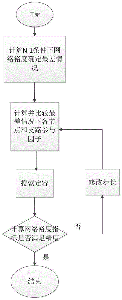
[0072] The present invention proposes and discloses a Facts equipment compensation method for improving the static safety margin of the power system under the N-1 condition. Judgment of nodes under poor conditions, get the site selection and fixed capacity of SVC and TCSC in the Facts equipment used for compensation, and achieve the purpose of improving the static safety margin of the power system.

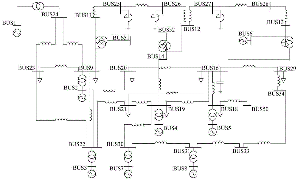
[0073] The method of the present invention takes as figure 1 The standard power system of the IEEE36 node shown is taken as an example for illustration.

[0074] Assume that the relationship between the active power and reactive power of the power system with respect to the phase angle and voltage is shown in formula (1):

[0075] Δ P ...


PUM


Abstract

The invention relates to a Facts equipment compensation method for improving static safety margin under the condition of N-1, and belongs to the technical field of power systems. The method achieves the judgment of nodes under the worst conditions through employing the selection and comparison of margin of a power system under the condition of N-1, obtains the site selection and constant volume of Facts equipment for compensation, and achieves a purpose of improving the static safety margin of the power system. The method specifically comprises the steps: selecting a node load as a margin index of a node, calculating margin indexes under all conditions of N-1, and finding out the worst condition and the worst node; obtaining a node with the maximum participation factor in the power system through comparison according to the size of participation factors of all nodes, and enabling the Facts equipment to be placed at the node with the maximum participation factor; solving a model formed by the above target function and constraint condition through a fixed point traversing method, and obtaining the constant volume of the Facts equipment. The method can improve the static safety stability of the power grid in the most effective manner, and is of great significance to a power grid operation dispatching department and the planning of the power grid.

Description

technical field [0001] The invention belongs to the technical field of power systems, and in particular relates to using Facts equipment to improve the margin index of the power system under the N-1 condition, thereby improving the stability of the power system. Background technique [0002] In the mid-1980s, Dr. N.G.Hingorani of the Electric Power Research Institute (EPRI) of the United States first proposed the concept of Flexible AC Transmission (FACTS): using high-power, high-performance power electronic components to make controllable active or reactive power supplies And the primary equipment of the power grid, etc., in order to realize the flexible control of the voltage, impedance, phase angle, power, power flow, etc. of the transmission system, and make the original basically uncontrollable power grid fully controllable, thereby greatly improving the flexibility and power of the power system. Stability greatly improves the transmission capacity of existing transmiss...

Claims


Application Information

Patent Timeline
IPC IPC(8): H02J3/16
CPCY02E40/30
Inventor 易俊王安斯顾卓远胡伟
Owner CHINA ELECTRIC POWER RES INST
Why Eureka
Try Eureka