Supercharge Your Innovation With Domain-Expert AI Agents!

Multi-branch outphasing system and method

一种多分支、异相的技术,应用在传输系统、带有半导体器件/放电管的放大器、门控放大器等方向

Active Publication Date: 2015-11-11
TEXAS INSTR INC
View PDF12 Cites 7 Cited by
  • Summary
  • Abstract
  • Description
  • Claims
  • Application Information

AI Technical Summary

Problems solved by technology

[0023] There is also an unmet need for improved multilevel out-of-phase power amplifiers that improve battery life in handheld devices

Method used


Image

  • Multi-branch outphasing system and method
  • Multi-branch outphasing system and method
  • Multi-branch outphasing system and method

Examples


Embodiment Construction

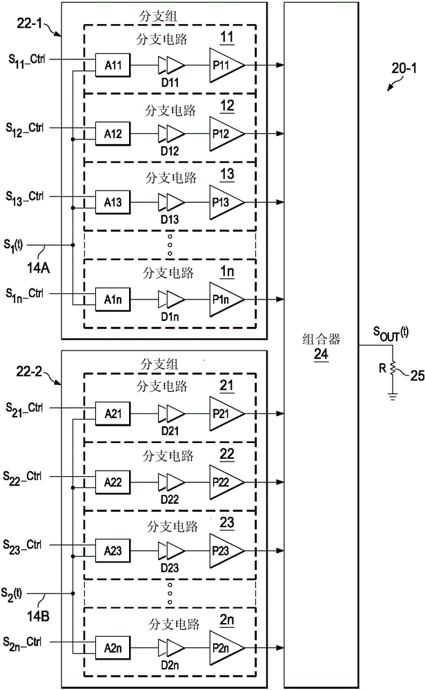
[0056] An asymmetric multilevel multibranch out-of-phase power amplifier includes multiple circuits, where each circuit includes a power amplifier (eg, a class E power amplifier) ​​and combiner circuitry coupled to an output of the power amplifier. The first RF drive signal is coupled to the inputs of all power amplifiers of the first set of branch circuits, and the second RF drive signal is coupled to the inputs of all power amplifiers of the second set of branch circuits. In one embodiment, each subcircuit in the first group includes an enable circuit or enable circuit that couples or enables a first drive signal to the first group of subcircuits in response to a corresponding selection control signal of the first group The input terminals of various power amplifiers in the Similarly, each subcircuit of the second group includes an enable circuit or an enable circuit that couples a second drive signal to the various power amplifiers in the second group of subcircuits in resp...


PUM


Abstract

A multi-level, multi-branch outphasing amplifier (20-1) includes a first branch group circuit (22-1) including a first branch circuit (11) receiving a first RF input signal (S1(t)) and first control information (S11—Ctrl=VDD) and a second branch circuit (12) receiving the first input signal and second control information (S12—Ctrl). Each of the first (11) and second (12) branch circuits includes a power amplifier. The second control information enables the second branch circuit to be switched on or off while the first branch circuit (12) remains on. A second branch group circuit (22-2) includes a third branch circuit (21) receiving a second RF input signal (S2(t)) and third control information (S21—Ctrl=VDD) and a fourth branch circuit (22) receiving the second input signal (S2(t)) and fourth control information (S22—Ctrl). Each of the third and fourth branch circuits includes a power amplifier. The fourth control information enables the fourth branch circuit to be switched on or off while the third branch circuit remains on. A combiner (24) combines output signals of the power amplifiers to produce an output signal (SOUT(t)).

Description

Background technique [0001] The present invention relates generally to multi-level out-of-phase power amplifiers, and more particularly to asymmetric multi-level multi-branch out-of-phase power amplifiers that have improved power efficiency and do not require switching between multiple supply voltages . [0002] A problem in the prior art is that the need for high data rates and efficient spectrum utilization in modem wireless communication systems results in a high peak-to-average power ratio of the modulated signal. This requires operating the associated RF power amplifier (PA) at a greatly reduced output power level for extended periods of time, known as large "powerback-off" operation. Conventional power amplifiers have lower efficiency (ie, the power delivered by the amplifier to the load divided by the total power consumed by the power amplifier) ​​under power backoff conditions than under peak output power conditions. [0003] In handheld devices, low power efficiency...

Claims


Application Information

Patent Timeline
Patent Type & Authority Applications(China)
IPC IPC(8): H03F3/20H03F1/02
CPCH04B1/1615H04B1/123H04B1/18H03F1/0277H03F1/0294H03F1/223H03F3/193H03F3/211H03F3/245H03F3/72H03F2200/411H03F2200/511H03F2200/541H03F2203/21136H03F2203/21142H03F2203/7215H03F2203/7236
Inventor A·班纳吉R·和扎尔L·丁N·R·舍姆
Owner TEXAS INSTR INC
Features
  • R&D
  • Intellectual Property
  • Life Sciences
  • Materials
  • Tech Scout
  • Unparalleled Data Quality
  • Higher Quality Content
  • 60% Fewer Hallucinations
Learn More