Capacitance multiplier and method

A capacitor and capacitor technology, applied in electrical components, impedance networks, conversion equipment without intermediate conversion to AC, etc., can solve problems such as limiting control loop bandwidth, impracticality, and large die area.

Active Publication Date: 2015-11-11
NXP BV
View PDF3 Cites 6 Cited by
  • Summary
  • Abstract
  • Description
  • Claims
  • Application Information

AI Technical Summary

Problems solved by technology

However, for circuits such as PWM boost regulators (or transformers), the control loop bandwidth is desirably limited due to the presence of right-hand plane (RHP) zeros
[0004] Although many solutions involve providing large value compensation capac

Method used


Image

  • Capacitance multiplier and method
  • Capacitance multiplier and method
  • Capacitance multiplier and method

Examples


Embodiment Construction

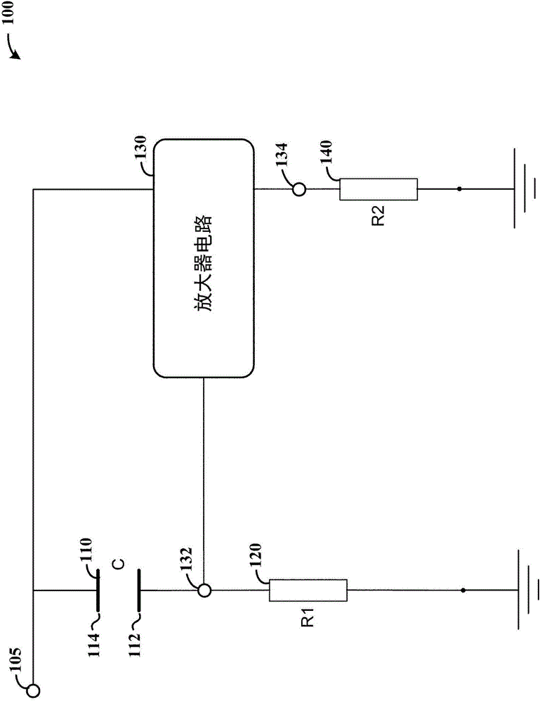
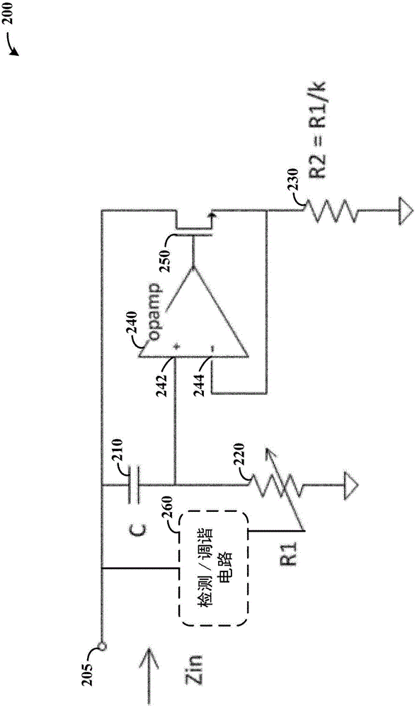
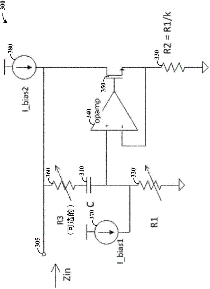
[0013] While the various embodiments discussed herein are intended to include various modifications and alternative forms, aspects of the embodiments are illustrated in the drawings and described in detail. It should be understood, however, that the intention is not to limit the invention to the particular embodiments described. On the contrary, the intention is to cover all modifications, equivalents, and alternatives falling within the scope of the present disclosure including aspects defined by the claims. Furthermore, the term "example" as used throughout this application is illustrative only and not intended to be limiting.

[0014] Aspects of the present disclosure are believed to be applicable to many different types of devices, systems and methods for providing multiplied capacitance, as may be implemented in multiple discrete circuits. Although not necessarily so limited, aspects of the invention can be appreciated through a discussion of the examples in this context...


PUM


Abstract

Capacitance multiplier circuitry provides an increased equivalent capacitance, and may be implemented using a desirably small footprint. As may be implemented in accordance with one or more embodiments, a capacitor provides a first capacitance across first and second plates, and capacitance multiplier circuitry operates with the capacitor to provide a second equivalent capacitance that is a multiple of the first capacitance. The capacitance multiplier circuitry includes a first circuit path having a first resistor between the first plate and a common terminal, and a second circuit path having a switch and a second resistor between the second plate and the common terminal. An amplifier has differential inputs respectively corresponding to the first and second circuit paths and provides the second equivalent capacitance by controlling operation of the switch based upon the differential inputs and the respective resistances provided by the resistors in the first and second circuit paths.

Description

technical field [0001] Various aspects of the embodiments relate to providing capacitance multiplication. Background technique [0002] Many circuit applications benefit from or require the use of capacitors in order to ensure proper operation. For example, narrowband loop compensation circuits, boost regulators, integrated pulse-width modulator (PWM) step-up transformers, LED drivers, and low-frequency phase-locked loops (PLLs) can benefit from the use of capacitors and associated circuitry. [0003] In circuit applications, such as those involving closed-loop control of integrated circuit systems, dominant poles are often created for stabilization purposes. Such a scheme can be implemented according to control theory in the frequency domain. This dominant pole can be created by on-chip capacitors and amplifiers such as transconductance amplifiers. A left hand plane (LHP) zero is also typically created to compensate for phase shift due to existing poles in the loop. How...

Claims


Application Information

Patent Timeline
IPC IPC(8): H03H11/46
CPCH03H11/483H02M3/07
Inventor 王戈
Owner NXP BV
Why Eureka
Try Eureka