
Anti-overflow rinsing device for lens

A cleaning device and anti-overflow technology, applied in the field of optical devices, can solve the problems of affecting the mood of the staff, aggravating the smell of the cleaning room, and failing to achieve the cleaning effect, and achieve the effects of good heating effect, high cleaning efficiency and uniform heating.

Inactive Publication Date: 2015-11-18
SUZHOU KAIDE MICRO ELECTRONICS CO LTD
View PDF10 Cites 3 Cited by
  • Summary
  • Abstract
  • Description
  • Claims
  • Application Information

AI Technical Summary

Problems solved by technology

[0002] At present, the current cleaning of the lens is placed in the cleaning tank, and the wax on the surface of the lens is peeled off by placing a liquid medicine in the cleaning tank, but after a period of time, the temperature of the liquid medicine drops, and the original excellent cleaning effect cannot be achieved. Therefore, A device that can heat the potion is needed so that the potion can exert the best effect and remove the wax on the lens to a great extent; in addition, the potion will volatilize after a period of time, causing the smell to diffuse, making the cleaning room The smell is aggravated, which affects the mood of the staff, and some potions contain substances that stimulate the human brain, and it is easy to cause dizziness after smelling them

Method used


Image

  • Anti-overflow rinsing device for lens

Examples


Embodiment Construction

[0012] The present invention will be further described below in conjunction with the accompanying drawings. The following examples are only used to illustrate the technical solution of the present invention more clearly, but not to limit the protection scope of the present invention.

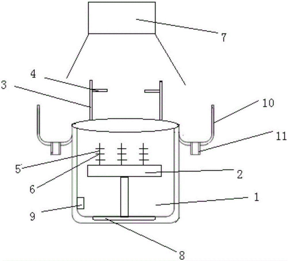
[0013] Such as figure 1 As shown, an anti-overflow lens cleaning device is characterized in that it includes a cleaning tank 1 and an upper cover, the cleaning tank 1 is connected with a pure water rinsing device, and the pure water rinsing device includes a lifting platform 2, a bracket 3. The nozzle 4 and the water storage tank, the lifting platform 2 is arranged inside the cleaning tank 1, the lens frame 5 is detachably connected to the lifting platform 2, and the lens frame 5 is provided with a plurality of fixing frames 6, the fixing frames 6. A plurality of lens fixtures are provided. The bracket 3 is arranged on the left and right sides of the cleaning tank 1. The nozzle 4 is fixed on th...


PUM


Abstract

The invention discloses an anti-overflow rinsing device for a lens. The anti-overflow rinsing device for the lens is characterized in that the anti-overflow rinsing device comprises a rinsing tank and an upper cover; the rinsing tank is connected with a pure water drip washing device; the pure water drip washing device comprises a lifting platform, supports, shower nozzles and a water storing tank; the lifting platform is arranged in the rinsing tank; lens racks are detachably connected on the lifting platform; a plurality of fixing frames are arranged on the lens racks; the fixing frames are provided with a plurality of lens clamps; the supports are arranged on the left and right sides of the rinsing tank; the shower nozzles are fixed on the supports and connected with the water storing tank through water pipes; a water pump is arranged in the water storing tank; the outer sides on the top edges of the rinsing tank are provided with U-shaped grooves; the sidewall heights of the most peripheral part of the U-shaped grooves are greater than the edge height of the top of the rinsing tank; the groove bottoms of the U-shaped grooves are provided with water outlets; the rinsing tank is further provided with a heating device; a controller is connected with the heating device and the pure water dip washing device and used for controlling the opening and closing of the upper cover.

Description

technical field [0001] The invention relates to the field of optical devices, in particular to an anti-overflow lens cleaning device. Background technique [0002] At present, the current cleaning of the lens is placed in the cleaning tank, and the wax on the surface of the lens is peeled off by placing a liquid medicine in the cleaning tank, but after a period of time, the temperature of the liquid medicine drops, and the original excellent cleaning effect cannot be achieved. Therefore, A device that can heat the potion is needed so that the potion can exert the best effect and remove the wax on the lens to a great extent; in addition, the potion will volatilize after a period of time, causing the smell to diffuse, making the cleaning room The aggravation of the smell of the medicine affects the mood of the staff, and some potions contain substances that stimulate the human brain, and it is easy to cause dizziness after smelling them. Contents of the invention [0003] T...

Claims


Application Information

Patent Timeline
Patent Type & Authority Applications(China)
IPC IPC(8): B08B3/02B08B3/10B08B15/02
CPCB08B3/02B08B3/10B08B15/02
Inventor 刘思佳
Owner SUZHOU KAIDE MICRO ELECTRONICS CO LTD
Learn More