Movable shears-fork type lift

A lift and scissor technology, applied in the field of mobile scissor lifts, can solve problems such as hidden safety hazards, large torque on rotating bearings, lift tilt, etc., and achieve the effects of improving loading and unloading efficiency, high loading and unloading stability, and small tire wear.

Inactive Publication Date: 2015-11-18
SHANDONG KINGELEVATOR GRP CO LTD
View PDF7 Cites 1 Cited by
  • Summary
  • Abstract
  • Description
  • Claims
  • Application Information

AI Technical Summary

Problems solved by technology

[0004] used in prior art figure 1 In the structure shown, it is necessary to ensure that the rotating shaft is set at the left and right centers of gravity of the elevator. The eccentric load will cause the rotating bearing to be subjected to a large torque, and the stability of the single-axis support is low.
figure 2 The loading and unloading scheme shown needs to be loaded and unloaded with the help of a crane, but when there is no crane or no hoisting holes are set, the forklift fork is in the blank space at the bottom of the frame, one is easy to damage the chassis structure, electrical and hydraulic components, but when fork loading It is not easy to find the center of gravity, causing the elevator to tilt, which poses a certain safety hazard

Method used


Image

  • Movable shears-fork type lift
  • Movable shears-fork type lift
  • Movable shears-fork type lift

Examples


Embodiment Construction

[0021] In order to better understand the present invention, the embodiments of the present invention will be explained in detail below with reference to the accompanying drawings.

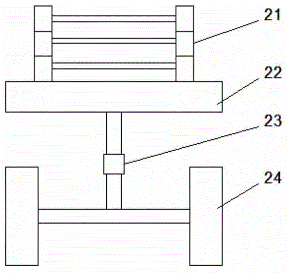
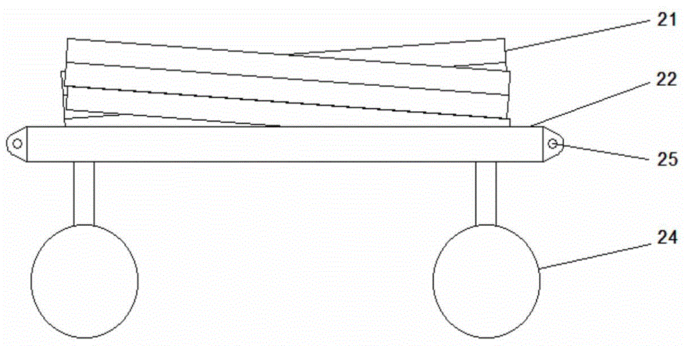
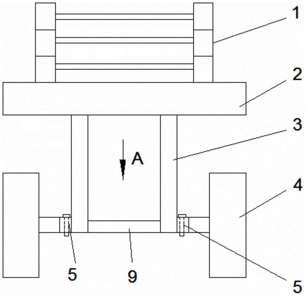
[0022] Such as Figure 3 to Figure 6 As shown, a mobile scissor lift includes a base frame 2, a front wheel 4, and a rear wheel 12. The upper part of the base frame 2 is provided with a scissor arm 1, and a bracket 11 is provided between the two scissor arms 1. The bottom of the underframe 2 is connected to the front axle 9 by a vertical support rod 3, the support rod 3 is provided with two, the front axle is provided with a rotating shaft 5 outside the support rod 3, and the front shaft 9 and the rotating shaft 5 are universal The outer end of the rotating shaft is connected with the front wheel 4, and the front wheel 4 is connected with the front wheel steering mechanism. The steering structure includes a trapezoidal arm 6, a tie rod 7, a shift fork 8, and the front end of the shift fork 8 is connec...


PUM


Abstract

The invention discloses a movable shears-fork type lift which comprises a chassis, front wheels and rear wheels. The upper portion of the chassis is provided with two shears-fork arms. A support is arranged between the two shears-fork arms. The bottom of the chassis is connected with a front shaft through vertical supporting rods. The movable shears-fork type lift is characterized in that the number of the supporting rods is two, the portions, on the outer sides of the supporting rods, of the front shaft are provided with rotating shafts, the front shaft is connected with the rotating shafts through universal joints, the outer ends of the rotating shafts are connected with the front wheels, the front wheels are connected with a front wheel steering mechanism which comprises a trapezoid arm, a transverse pull rod and a shifting fork, the front end of the shifting fork is connected with the inner end of the transverse pull rod, the outer end of the transverse pull rod is hinged to the front end of the trapezoid arm, the rear end of the trapezoid arm is connected with the front wheels, the rear end of the shifting fork is connected with the steering transverse pull rod through a pin shaft, the middle of the shifting fork is in bearing connection with the front shaft, the shifting fork is shifted to rotate so as to drive the steering transverse pull rod to rotate, and the transverse pull rod drives the wheels to rotate. According to the movable shears-fork type lift, the rotating angles of the left front wheel and the right front wheel meet the Ackman theorem, tire abrasion is small, the assembling and disassembling efficiency is high, and safety and reliability are high.

Description

Technical field [0001] The invention relates to the technical field of aerial work equipment, in particular to a mobile scissor lift. Background technique [0002] The scissor lift is a special equipment for high-altitude operations with a wide range of uses. The chassis of the scissor lift carries the scissor arm, the working platform and the upper load, and its stability determines the stability of the entire lift. In addition, the mobile scissor lift itself cannot be transported over long distances. Long-distance transport requires auxiliary transport vehicles, so the convenience of hoisting or loading and unloading is particularly important. [0003] The commonly used mobile scissor lift chassis structure in the prior art is such as figure 1 , figure 2 Shown. Including scissor arm 21, underframe 22, rotating shaft 23, front wheel 24, hoisting hole 25, figure 1 Shown is a schematic diagram of the front axle support. The front axle of the chassis is supported by a single axle,...

Claims


Application Information

Patent Timeline
Patent Type & Authority Applications(China)
IPC IPC(8): B66F11/00
CPCB66F11/00
Inventor 付风超方新
Owner SHANDONG KINGELEVATOR GRP CO LTD
Why Eureka
Try Eureka