Airflow twisting device provided with filter net and driven by lifting motor to lift for textile

A lifting motor and filter screen technology, used in textiles and papermaking, open-end spinning machines, continuous winding spinning machines, etc. Easy to find and other problems, to achieve the effect of stable and reliable device structure, reduced transmission links, and compact structure

Inactive Publication Date: 2015-11-18
杨田花
View PDF10 Cites 2 Cited by
  • Summary
  • Abstract
  • Description
  • Claims
  • Application Information

AI Technical Summary

Problems solved by technology

[0003] However, with the increase of the airflow passages in the tangential direction and the reduction of the diameter of the passages, the blockage of the airflow passages is more likely to occur.
[0004] Due to the characteristics of the high-speed operation of the airflow and the large number of airflow channels, the blockage of the airflow channel is often not easy to be found and it is not easy to overcome or correct it immediately.
This leads to quality defects in continuous textile production
Downtime for maintenance reduces productivity and incurs additional production costs

Method used


Image

  • Airflow twisting device provided with filter net and driven by lifting motor to lift for textile
  • Airflow twisting device provided with filter net and driven by lifting motor to lift for textile
  • Airflow twisting device provided with filter net and driven by lifting motor to lift for textile

Examples


Embodiment Construction

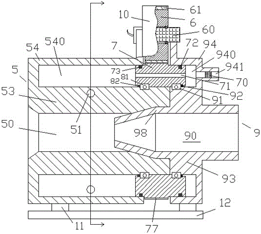
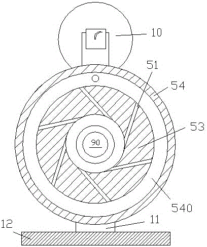
[0012] Combine below Figure 1-3 The present invention will be described in detail.

[0013] An air-flow twisting device for textiles driven by a lifting motor and with a filter screen, used to twist rovings, including a vortex air-flow twisting device 5, the vortex air-flow twisting device 5 includes a cylindrical The annular body portion 53 of the vortex air chamber 50 and the integrally formed annular housing portion 54 that accommodates the annular body portion 53, the annular body portion 53 is provided with a plurality of tangential gas strips uniformly distributed along the circumferential direction The channel 51 is used to input airflow along the tangential direction of the cylindrical vortex air chamber 50, and an annular airflow distribution chamber 540 is formed between the annular shell part 54 and the annular body part 53 for receiving The airflow is input and distributed to the plurality of tangential air passages 51. The left end of the airflow distribution ch...


PUM


Abstract

The invention discloses an airflow twisting device provided with a filter net and driven by a lifting motor to lift for textile. The airflow twisting device is used for twisting a thick yarn and comprises a vortex airflow twisting device (5), wherein the vortex airflow twisting device (5) comprises an annular body part (53) and an annular housing part (54), wherein a cylindrical vortex air chamber (50) is arranged in the annular body part (53); the annular housing part (54) and the annular body part (53) are integrally molded; the annular housing part (54) accommodates the annular body part (53); a plurality of tangential airways (51) which are evenly distributed along the peripheral direction are formed in the annular body part (53) to input the airflow along the tangential direction of the cylindrical vortex air chamber (50); and an annular airflow distribution chamber (540) is formed between the annular housing part (54) and the annular body part (53).

Description

technical field [0001] The application relates to the field of textile machinery, in particular to an air-twisting device for textile use which is lifted and lowered by a lifting motor and equipped with a filter. Background technique [0002] In the textile field, the twisting of the roving is often carried out by swirling air. Such a swirling airflow can be achieved by swirling in the swirling chamber with a plurality of tangentially supplied airflows. [0003] However, as the number of airflow passages in the tangential direction increases and the diameter of the passages decreases, the blockage of the airflow passages is more likely to occur. [0004] Due to the characteristics of the high-speed operation of the airflow and the large number of airflow passages, the blockage of the airflow passages is often not easy to be found and cannot be overcome or corrected immediately. This leads to quality defects in continuous textile production. Downtime for maintenance reduce...

Claims


Application Information

Patent Timeline
Patent Type & Authority Applications(China)
IPC IPC(8): D01H4/02
Inventor 杨田花
Owner 杨田花
Why Eureka
Try Eureka