An industrial sewing machine tape type fabric suction cup

An industrial sewing machine and tape technology, applied in sewing machine components, sewing equipment, cloth feeding mechanisms, etc., can solve problems such as the inability to send the cloth to the required processing position, the trouble of automatic processing of industrial sewing machines, and the relative displacement between the cloth and the suction cup. , to achieve the effect of convenient implementation, ingenious design and simple structure

Active Publication Date: 2017-06-27
SHANGHAI WEISHI MACHINERY
View PDF4 Cites 0 Cited by
  • Summary
  • Abstract
  • Description
  • Claims
  • Application Information

AI Technical Summary

Problems solved by technology

[0003] The technical problem to be solved by the present invention is that the cloth and the suction cup of the existing industrial sewing machine are prone to relative displacement when moving laterally, and the cloth cannot be accurately sent to the required processing position; or the suction is difficult to control, not Unable to absorb means that multiple pieces of fabric are absorbed at one time, which brings troubles to the automatic processing of industrial sewing machines

Method used


Image

  • An industrial sewing machine tape type fabric suction cup
  • An industrial sewing machine tape type fabric suction cup

Examples


Embodiment Construction

[0020] The present invention will be further described below in conjunction with the accompanying drawings and specific embodiments.

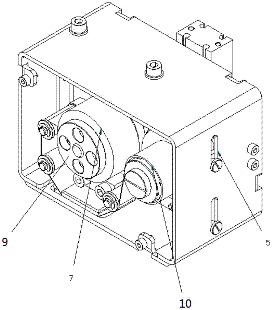
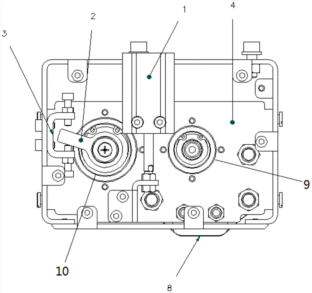
[0021] see Figure 1-Figure 2 , an industrial sewing machine tape-type cloth sucker, said comprising a housing, a cylinder 1 is vertically installed in said housing, said cylinder 1 telescopic ejector rod is fixedly connected with a tape rotating mechanism 4, and said tape rotating mechanism 4 is mounted on the cylinder 1 Driven to move up and down along the guide grooves 5 on both sides of the housing; the one-way wheel 10 and the driven wheel 9 are fixed on the tape rotation mechanism 4, the one-way wheel has a rocker arm 2, and the housing is equipped with a limiting member 3, the The rocker arm 2 is located in the upper and lower intervals of the limiting member 3; the adhesive tape 7 is wound on the one-way wheel 10 and the driven wheel 9, and the inner side of the adhesive tape is slidably attached to the suction cup 8, and the suction cu...


PUM


Abstract

The invention relates to a tape-type cloth sucker for an industrial sewing machine, which comprises a shell, in which a cylinder is vertically installed, and the telescopic ejector rod of the cylinder is fixedly connected with a tape rotating mechanism, and the tape rotating mechanism is driven by the cylinder to move up and down along the guide grooves on both sides of the shell Movement; the one-way wheel and the driven wheel are fixed on the tape rotation mechanism, the one-way wheel has a rocker arm, the housing is equipped with a limit member, and the rocker arm is located in the upper and lower intervals of the limit member; the tape is wound on the one-way wheel and the driven wheel , the inner side of the tape slides and fits with the suction cup, and the suction cup is connected to the lower part of the tape rotation mechanism; the rotation mechanism 4 is lifted up, and under the relative outward force of the shell, the cloth and the tape are separated and fall into the required area to implement the detachment action; At the same time, the rocker arm rotates positively under the action of the limiting member, and the forward rotation of the one-way wheel drives the tape to advance to the length of a suction cup; the rotating mechanism is pressed down, and the rocking arm rotates freely in the reverse direction under the action of the limiting member, and the adsorption action is carried out. , the one-way wheel reverses and resets freely.

Description

technical field [0001] The invention relates to an industrial sewing machine cloth suction cup, in particular to a tape-type cloth suction cup for an industrial sewing machine, which belongs to the technical field of industrial sewing machine suction cups. Background technique [0002] The cloth grab suction cups of the existing industrial sewing machines generally have two forms. One is to use a non-contact suction cup. The bottom of the suction cup is blown obliquely to generate a local negative pressure, thereby suspending and adsorbing the cloth. However, when the suction cup moves laterally The cloth and the suction cup are prone to relative displacement, so the cloth cannot be accurately sent to the position to be processed; the other is the pure vacuum suction cup type, but the vacuum suction cup type is difficult to control the suction force because it directly vacuums the cloth. For some fabrics, it either cannot absorb or absorbs multiple pieces of fabric at one ti...

Claims


Application Information

Patent Timeline
Patent Type & Authority Patents(China)
IPC IPC(8): D05B35/00
Inventor 马振雷柴国宣
Owner SHANGHAI WEISHI MACHINERY
Why Eureka
Try Eureka