
Implantable pole sleeve butt joint structure and cabinet adopting implanted pole sleeve joint structure

An implanted, rod-sleeve technology, applied in the field of cabinets, can solve the problems of unsatisfactory surface quality of finished products, limited surface aesthetics, and sunken furniture panels, and achieves simple and stable assembly process, good connection effect, and fewer knocks. Effect

Active Publication Date: 2017-05-24
宁波捷丰现代家俱有限公司
View PDF7 Cites 0 Cited by
  • Summary
  • Abstract
  • Description
  • Claims
  • Application Information

AI Technical Summary

Problems solved by technology

At present, the connection between furniture panels is basically realized by nails or tenons. If the connection is made by nails, the surface aesthetics is limited, and the number of knocks is too many, which is easy to accidentally damage the board surface. If it is connected by tenons, it needs to be used every time. It is inconvenient to knock the panel too hard to complete the assembly, and too many times of knocking can easily cause dents and damage to the furniture panel, resulting in unsatisfactory surface quality of the finished product

Method used


Image

  • Implantable pole sleeve butt joint structure and cabinet adopting implanted pole sleeve joint structure
  • Implantable pole sleeve butt joint structure and cabinet adopting implanted pole sleeve joint structure
  • Implantable pole sleeve butt joint structure and cabinet adopting implanted pole sleeve joint structure

Examples


Embodiment Construction

[0027] The present invention will be further described below in conjunction with the accompanying drawings and specific embodiments.

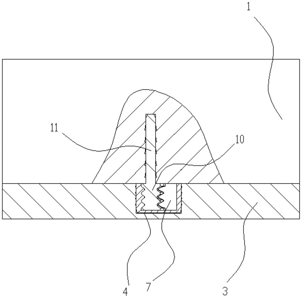
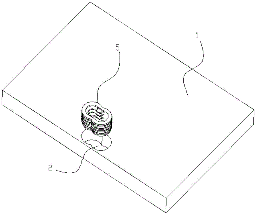
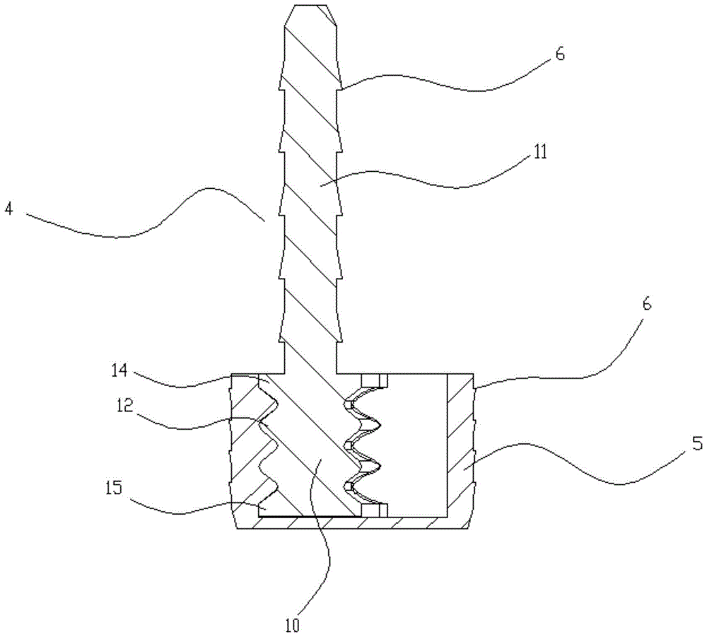
[0028] Such as Figure 1 to Figure 9 In the shown embodiment, an implantable rod sleeve docking structure includes an insert groove 2 provided on the first plate 1, a convex piece groove provided on the second plate 3, and the insert groove is provided with The connecting kit, the protruding part groove is provided with implanted convex parts 4, the connecting kit includes the buckle base sleeve 5, and the outer wall of the buckle base sleeve is provided with a number of connection barb rings 6, and the connection on the buckle base sleeve The barb ring and the side wall of the insert groove are pressed against each other. The buckle base sleeve is provided with a buckle groove. There are several C-shaped buckles 9 arranged in parallel in the half groove, and the space between adjacent C-shaped buckles is a snap-in gap. The implanted convex pa...


PUM


Abstract

The invention discloses an implanted type rod-sleeve butt-joint structure and aims to provide a double-panel connecting structure which is reasonable in structure, enables furniture panels to be quickly connected in a butt-joint mode and assembled, enables assembling operation to be convenient and is good in connecting effect. The implanted type rod-sleeve butt-joint structure comprises an insert groove formed in a first panel and a convex piece groove formed in a second panel. A connecting sleeve piece is arranged in the insert groove, and an implanted convex piece is arranged on the convex piece groove. The connecting sleeve piece comprises a base buckling sleeve, and a plurality of connecting barb rings are arranged on the outer side wall of the base buckling sleeve. The connecting barb rings on the base buckling sleeve and the side wall of the insert groove are pressed tightly. A buckling groove is formed in the base buckling sleeve and composed of a pre-implanting half groove and a locating half groove, a plurality of C-shaped buckling pieces are arranged in the locating half groove, and the spaces between the adjacent C-shaped buckling pieces are clamping-in gaps. The implanted convex piece comprises a buckle section and a connecting panel section, wherein the buckle section is provided with clamping-in annular protrusions matched with the clamping-in gaps, and the connecting panel section is provided with a plurality of connecting barb rings; the connecting panel section is located in the convex piece groove, and the connecting barb rings on the connecting panel section and the side wall of the convex piece groove are pressed tightly.

Description

technical field [0001] The invention belongs to the technical field of cabinet furniture, and in particular relates to an implanted rod sleeve butt joint structure and a cabinet adopting the implanted rod sleeve butt joint structure. Background technique [0002] With the advancement of technology and the increase of demand, there are more and more types of furniture, and various cabinets and cabinets emerge in endlessly. However, most cabinet furniture is formed by installing and separating multiple furniture panels, and the external panels constitute the main body. , the interior panels divide the interior space. At present, the connection between furniture panels is basically realized by nails or tenons. If the connection is made by nails, the surface aesthetics is limited, and the number of knocks is too many, which is easy to accidentally damage the board surface. If it is connected by tenons, it needs to be used every time. It is inconvenient to knock the panel too ha...

Claims


Application Information

Patent Timeline
Patent Type & Authority Patents(China)
IPC IPC(8): F16B12/10A47B96/00
CPCA47B96/00F16B12/10
Inventor 鲍向前
Owner 宁波捷丰现代家俱有限公司
Learn More