
Fault monitoring device and method, air conditioning unit and air conditioner

A fault monitoring and unit technology, applied in the control field, can solve problems such as inability to achieve early warning protection, and achieve the effect of preventing faults.

Active Publication Date: 2015-11-18
GREE ELECTRIC APPLIANCES INC
View PDF7 Cites 4 Cited by
  • Summary
  • Abstract
  • Description
  • Claims
  • Application Information

AI Technical Summary

Problems solved by technology

Therefore, effective early warning protection cannot be realized

Method used


Image

  • Fault monitoring device and method, air conditioning unit and air conditioner
  • Fault monitoring device and method, air conditioning unit and air conditioner
  • Fault monitoring device and method, air conditioning unit and air conditioner

Examples


Embodiment Construction

[0053] The following will clearly and completely describe the technical solutions in the embodiments of the present invention with reference to the accompanying drawings in the embodiments of the present invention. Obviously, the described embodiments are only some, not all, embodiments of the present invention. The following description of at least one exemplary embodiment is merely illustrative in nature and in no way taken as limiting the invention, its application or uses. Based on the embodiments of the present invention, all other embodiments obtained by persons of ordinary skill in the art without creative efforts fall within the protection scope of the present invention.

[0054] The relative arrangements of components and steps, numerical expressions and numerical values ​​set forth in these embodiments do not limit the scope of the present invention unless specifically stated otherwise.

[0055] At the same time, it should be understood that, for the convenience of d...


PUM


Abstract

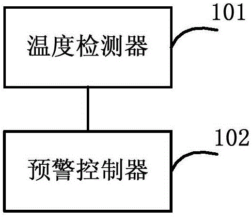
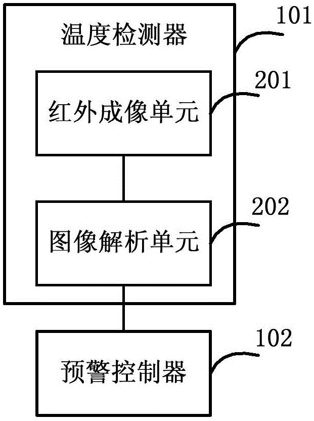
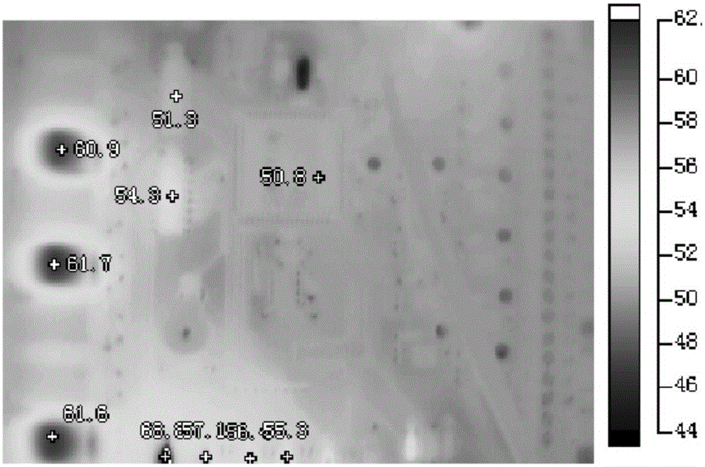
The invention discloses a fault monitoring device and method, an air conditioning unit and an air conditioner. The method comprises the steps that a temperature detector detects current temperature values of all parts in the unit in real time, an early warning controller judges whether an early warning part exists according to a detection result, and if the early warning part exists, early warning processing is performed, wherein the current temperature value of the early warning part is larger than the upper temperature limit corresponding to the early warning part itself. According to the fault monitoring device and method, the air conditioning unit and the air conditioner, the current temperature of all the parts is detected, early warning processing is performed when the current temperature of the part exceeds the corresponding temperature threshold, and therefore passive processing of faults can be converted into active prevention of the faults.

Description

technical field [0001] The invention relates to the field of control, in particular to a fault monitoring device and method, an air conditioner unit and an air conditioner. Background technique [0002] At present, the electronic control components of large central air-conditioning units are often damaged due to factors such as short circuit, overload, or continuous high-temperature operation, and the components cannot be restored. In addition, the connecting wire used in the current electric control box may also have a small wire diameter or an excessively large resistance, which may cause the temperature to continue to rise, and eventually cause the wire to be overheated until it burns. The precursor to these failures is often abnormally high temperature. [0003] In order to overcome this defect, currently there is a way of detecting the temperature of the unit through a temperature sensor in the prior art for safety warning. But the working temperature of different par...

Claims


Application Information

Patent Timeline
IPC IPC(8): F24F11/00
CPCF24F11/30F24F11/32F24F2110/10
Inventor 明开云钟荣涂连军李国耀赖元华丁亚斌樊钊黎阳刘振邦敖道满
Owner GREE ELECTRIC APPLIANCES INC
Learn More