
Method for controlling temperature and humidity in electricity motor room

A technology for humidity control and computer room, applied in heating and ventilation control system, control input related to air characteristics, space heating and ventilation control input, etc. problems, problems that cannot be resolved quickly, etc.

Inactive Publication Date: 2015-11-18
STATE GRID SHANDONG ELECTRIC POWER
View PDF0 Cites 11 Cited by
  • Summary
  • Abstract
  • Description
  • Claims
  • Application Information

AI Technical Summary

Problems solved by technology

[0007] 1. When an abnormality occurs, the management personnel will go to the scene to deal with it. If the management personnel cannot rush to the scene immediately due to special reasons, the abnormal situation will continue to occur before the management personnel arrives at the scene, and the normal and stable operation of the equipment in the computer room cannot be guaranteed;
[0008] 2. Both temperature and humidity have a threshold range for normal operation. When the temperature and humidity in the computer room change rapidly in a short period of time, for example, when the server in the computer room has a relatively large load in a short period of time and the temperature changes quickly, if in this case After the alarm is issued, the equipment may have returned to normal after the management personnel arrive at the scene, so there is no need for personnel to perform any processing operations, which is a waste of manpower;
[0009] 3. If there is an alarm and the management personnel arrive at the scene, they find that there is a problem with the air conditioner, humidification and dehumidification equipment. If there is no spare air conditioner, humidification and dehumidification equipment, the problem cannot be solved quickly

Method used


Image

  • Method for controlling temperature and humidity in electricity motor room

Examples


Embodiment Construction

[0021] The specific implementation manners of the present invention will be described in detail below in conjunction with the accompanying drawings.

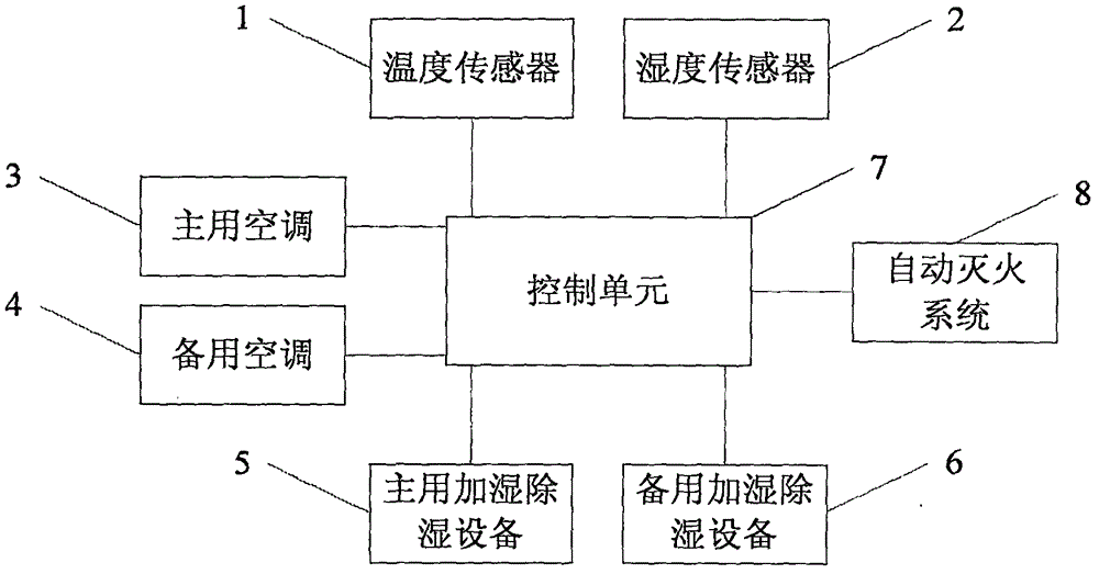
[0022] A method for controlling temperature and humidity in a power machine room. The power machine room includes a plurality of temperature sensors 1 and a plurality of humidity sensors 2 densely installed, a main air conditioner 3, a backup air conditioner 4, a main humidification and dehumidification device 5, and a backup humidification and dehumidification device. Equipment 6, control unit 7 and automatic fire extinguishing system 8.

[0023] The temperature sensor and the humidity sensor monitor the temperature and humidity in the computer room in real time, and transmit the monitoring results to the control unit.

[0024] When a fire occurs in the computer room, emergency treatment is required. The occurrence of fire may cause the temperature sensed by the temperature sensor near the ignition point to rise sharply. When...


PUM


Abstract

The invention relates to a method for controlling temperature and humidity in an electricity motor room. The electricity motor room comprises multiple densely-distributed temperature sensors, multiple densely-distributed humidity sensors, a main air conditioner, a standby air conditioner, a main humidification and dehumidification device, a standby humidification and dehumidification device, a control unit and an automatic fire extinguishing system. When it is judged that the time of an abnormal accident is short, no treatment is carried out; when it is judged that the time of an abnormal accident is long, the standby treatment devices can be started for treatment. In this way, the abnormal condition can be flexibly treated, a manager can be informed in time when the abnormal condition occurs, the condition that the manager does not need to reach the site can be treated, and manpower is reduced.

Description

technical field [0001] The invention relates to a temperature and humidity control method in an electric machine room, in particular to a method for precisely controlling the temperature and humidity in an electric machine room. Background technique [0002] Power supply is one of the basic guarantees for social production and people's lives. With the steady development of the economy, the demand for power is also increasing. Therefore, the safe and normal operation of the power system directly affects the realization of production and management goals. Safety management of power system computer room. [0003] With the development of technology, in order to realize the safety management of the power system computer room, the Internet of Things is introduced into it. The Internet of Things (The Internet of Things) is to connect all items to the Internet through radio frequency identification and other information sensing devices to realize intelligent identification and mana...

Claims


Application Information

Patent Timeline
Patent Type & Authority Applications(China)
IPC IPC(8): F24F11/00
CPCF24F2110/20F24F11/30F24F11/33F24F2110/10
Inventor 刘力军薛峰王西芝毕学奎刘泽楷王晓云段元栋闫传文李兴业刘峰
Owner STATE GRID SHANDONG ELECTRIC POWER
Learn More