High Q value micro-machined gyroscope structure based on nanometer grating detection

A micro-mechanical gyroscope and nano-grating technology, applied in the field of micro-inertial navigation, can solve the problems of small Q value and large damping coefficient, and achieve the effect of reducing the damping coefficient of the synovial film, high sensitivity, and increasing structural sensitivity

Active Publication Date: 2015-11-18
ZHONGBEI UNIV
View PDF5 Cites 14 Cited by
  • Summary
  • Abstract
  • Description
  • Claims
  • Application Information

AI Technical Summary

Problems solved by technology

[0004] The invention aims to solve the problem that the damping coefficient between the double-layer structure of the micro-mechanical gyroscope based on nano-grating detection is too large and the Q value is too small

Method used


Image

  • High Q value micro-machined gyroscope structure based on nanometer grating detection
  • High Q value micro-machined gyroscope structure based on nanometer grating detection
  • High Q value micro-machined gyroscope structure based on nanometer grating detection

Examples


Embodiment Construction

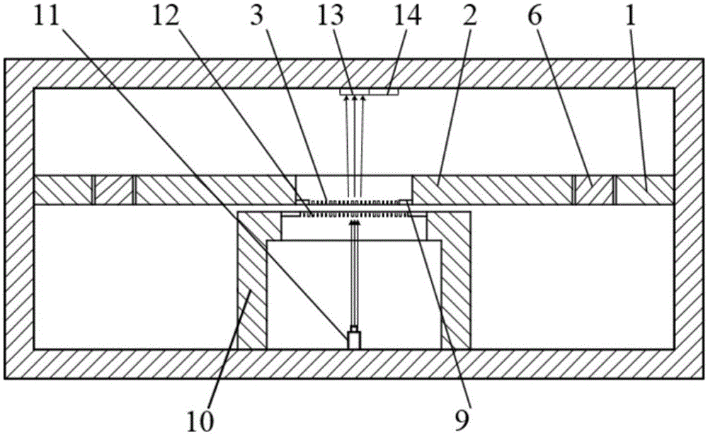
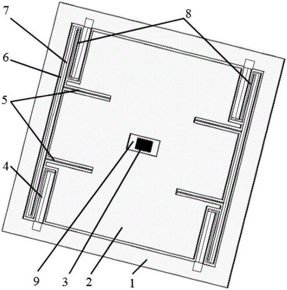
[0026] The present invention will be described in further detail below with reference to the drawings and embodiments, examples of the embodiments are shown in the drawings, wherein the same or similar reference numerals represent the same or similar elements or elements with the same or similar functions. The embodiments described below by referring to the figures are exemplary only for explaining the present invention and should not be construed as limiting the present invention.

[0027] In the present invention, it needs to be explained that the orientations or positional relationships indicated by the terms "center", "upper", "lower", "front", "rear", "left", "right" etc. are based on the drawings The orientation or positional relationship shown is only for the convenience of describing and simplifying the description of the present invention, but does not indicate or imply that the structure or element referred to must have a specific orientation, be constructed and opera...


PUM


Abstract

The present invention relates to the micro inertial navigation technology related field, particularly to a high Q value micro-machined gyroscope structure based on nanometer grating detection, wherein the micro-machined gyroscope structure is provided with a boss provided with a fixed nanometer grating, and with the boss, the overlapping area between the lower layer fixed structure and the upper layer movable structure can be reduced. According to the present invention, the lower layer fixed grating is arranged on the boss so as to reduce the overlapping area between the lower layer fixed structure and the upper layer movable structure; when the mass block of the micro-machined gyroscope produces the horizontal displacement under the effect of Coriolis force, the slide film damping coefficient between the upper layer structure and the lower layer structure is substantially reduced, such that the sensitivity of the micro-machined gyroscope structure is increased, wherein the structure sensitivity of the micro-machined gyroscope based on the nanometer grating detection is increased by 1-2 orders of magnitude; and the whole structure is compact, and the structure has the high sensitivity.

Description

technical field [0001] The invention relates to the related field of micro-inertial navigation technology, in particular to a high-Q micro-mechanical gyroscope structure based on nano-grating detection. Background technique [0002] The core technology of the micromechanical gyro is to detect the micro-stress or micro-displacement caused by the weak Coriolis force. With the miniaturization of devices, there are more and more detection limitations, which limit the further improvement of gyroscope detection sensitivity. At present, the micro-mechanical gyroscopes mainly include piezoresistive micro-mechanical gyroscopes, capacitive micro-mechanical gyroscopes, piezoelectric micro-mechanical gyroscopes, and quartz micro-mechanical gyroscopes. The sensitivity of the piezoresistive micromachined gyroscope is low, and the inherent temperature effect greatly limits its application. At present, the widely used micromachined gyroscope is the capacitive micromachined gyroscope, but w...

Claims


Application Information

Patent Timeline
Patent Type & Authority Applications(China)
IPC IPC(8): G01C19/5649G01C19/5656
CPCG01C19/5649G01C19/5656
Inventor 李孟委王宾王莉褚伟航刘俊
Owner ZHONGBEI UNIV
Why Eureka
Try Eureka