Touch panel and display apparatus

A touch panel and touch position technology, which is applied to instruments, electrical digital data processing, and data processing input/output processes, etc., can solve the problems of low light transmittance, low touch position accuracy, and touch media Restricted and other problems, to achieve the effect of high light transmittance, less interference from external signals, and improved brightness

Inactive Publication Date: 2017-07-07
BOE TECH GRP CO LTD +1
View PDF3 Cites 10 Cited by
  • Summary
  • Abstract
  • Description
  • Claims
  • Application Information

AI Technical Summary

Problems solved by technology

[0005] Aiming at the above-mentioned deficiencies in the prior art, the present invention provides a touch panel and a display device, which are used to at least partially solve the limitation of the touch medium, the low light transmittance, and the judgment of the touch position of the existing touch panel. The problem of low accuracy

Method used


Image

  • Touch panel and display apparatus
  • Touch panel and display apparatus

Examples


Embodiment Construction

[0028] In order for those skilled in the art to better understand the technical solutions of the present invention, a touch panel and a display device provided by the present invention will be described in detail below with reference to the accompanying drawings.

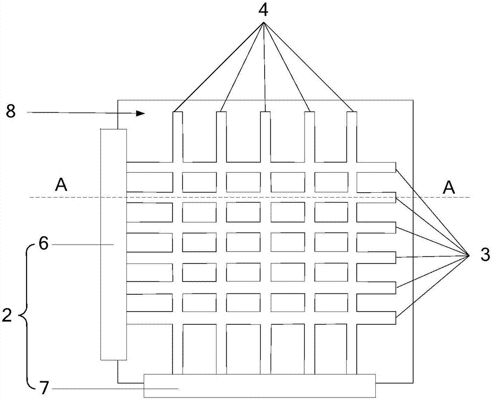
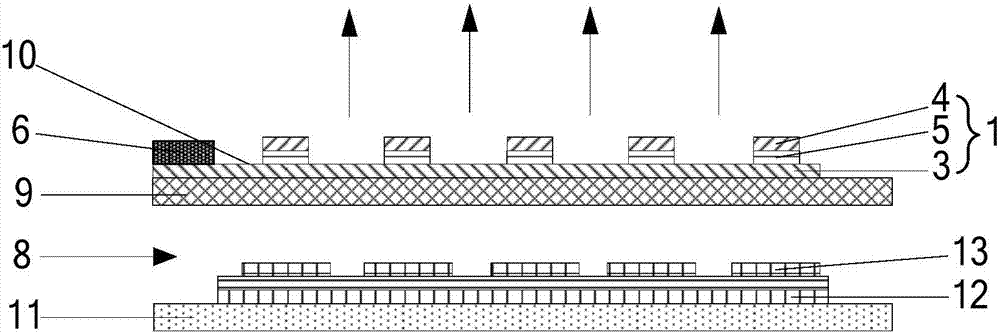
[0029] combine figure 1 and figure 2 As shown, the touch panel provided by the embodiment of the present invention includes: a pressure sensor 1 and a detection unit 2. The pressure sensor 1 includes: a plurality of first electrodes 3 parallel to each other and a plurality of second electrodes 4 parallel to each other. The piezoelectric layer 5 between the first electrode 3 and the second electrode 4, the first electrode 3 and the second electrode 4 are overlapped, and the piezoelectric layer 5 is located at the position where the first electrode 3 and the second electrode 4 overlap, with It is used to convert the pressure signal acting on it into a voltage signal and send it to the first electrode 3 and the secon...


PUM


Abstract

The invention provides a touch panel and a display apparatus. The touch panel is provided with a pressure sensor and a detection unit; and the pressure sensor comprises a plurality of first electrodes parallel to one another, a plurality of second electrodes parallel to one another, and piezoelectric layers located between the first electrodes and the second electrodes. When external force acts on the surface of the touch panel, the piezoelectric layers convert a pressure signal on the touch panel into a voltage signal and send the voltage signal to the first electrodes and the second electrodes; and the detection unit determines a touch position according to the voltage signal on the first electrode and the second electrode. The touch position is determined through the pressure acting on the pressure sensor, and a touch medium is not limited, so that the application range is relatively wide; moreover, the first electrodes and the second electrodes are strip-shaped electrodes arranged in a crossover manner, and light transmissivity is relatively high, so that the brightness of the touch panel can be improved; and in addition, the crossover areas between the first electrodes and the second electrodes are relatively small and difficultly disturbed by external signals, so that the accuracy of touch position judgment can be improved.

Description

technical field [0001] The present invention relates to the technical field of touch display, in particular to a touch panel and a display device. Background technique [0002] Due to the advantages of better convenient operation, better user experience and larger screen size, the touch panel is widely used. Existing mainstream touch panels usually use resistive touch sensors or capacitive touch sensors. The resistive touch sensor includes a first electrode layer and a second electrode layer, and the first electrode layer and the second electrode layer are insulated and separated by Evenly spaced transparent grid dividers. When an external force acts on the surface of the touch sensor, the first electrode layer on the upper layer deforms and contacts the second electrode layer, making the first electrode layer and the second electrode layer conductive and generating a potential difference, so that the detection module can The touch position is calculated from the potential...

Claims


Application Information

Patent Timeline
Patent Type & Authority Applications(China)
IPC IPC(8): G06F3/041
CPCG06F3/0414G06F3/0412G06F2203/04105
Inventor 李志勇齐智坚李云泽杨妮
Owner BOE TECH GRP CO LTD
Why Eureka
Try Eureka